In previous articles, we have mentioned the use of BFD – Bidirectional Forwarding Detection. RFC 5880.
Essentially BGP failure detection is slow by design and for good reason when you are dealing with truly massive networks. BFD exists to make it fast, but also while being safe too.
As was discussed in previous articles BGP detects failures slowly, by default the Keepalive Timer is 60 seconds, the Hold Timer is 180 seconds. Which means if a link silently fails, i.e. it stays up (no TCP reset) but stops forwarding traffic it may take up to 180 seconds for BGP to declare the neighbour dead and start to re-route traffic. Behaviour such as this is fine for Internet-Scale stability but is not fine for Data Centres, Core Networks or Low-Latency environments.
As mentioned before, you can tweak the Keepalive and Hold Timers to reduce this time, but the shorter the time, the more “twitchy” your network becomes to failed or flapping links.
BFD (Bidirectional Forwarding Detection) can be used to resolve these issues. It is a lightweight protocol, which is designed specifically to detect link/forwarding failures, and it is independent of any routing protocol, meaning you can use it with BGP, OSPF, EIGRP or even static routes, and provides an extremely fast (potentially sub-second) protocol.
Put in simple terms BFD is a heartbeat protocol that various routing protocols (such as BGP, OSPF or EIGRP) can subscribe to be informed of if a neighbour is dead, long before the mechanisms of the actual routing protocol kick in.
BFD does not exchange routes, it just says: “Forwarding to this neighbour is working” or “Forwarding is broken”, the routing protocol above, then acts based on this.
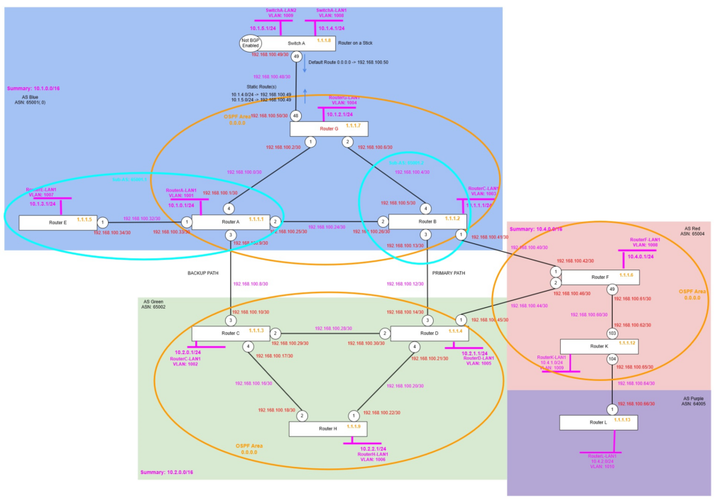
Topology
We will be setting up BFD between Router K and Router L, because these are the only two Routers we have that are sufficiently new to have software support for BFD!
Topology Changes
We had a problem with Router K, so it needed to be replaced, so the port numbers had to change, the configuration needed to be re-applied and use different ports, however the rest of the configuration on Router F and Router L remained as it was.
create vlan "RouterK-LP"
configure vlan RouterK-LP tag 1212
enable loopback-mode vlan RouterK-LP
configure vlan RouterK-LP ipaddress 1.1.1.12 255.255.255.255
enable ipforwarding vlan RouterK-LP

create vlan "RK-RF"
configure vlan "RK-RF" ipaddress 192.168.100.62/30
enable ipforwarding vlan "RK-RF"
configure vlan "RK-RF" add port 103 untagged

create vlan "RK-RL"
configure vlan "RK-RL" ipaddress 192.168.100.65/30
enable ipforwarding vlan "RK-RL"
configure vlan "RK-RL" add port 104 untagged

create vlan "RouterK-LAN1" tag 1009
configure vlan "RouterK-LAN1" ipaddress 10.4.1.1/24
enable ipforwarding "RouterK-LAN1"
enable loopback-mode vlan "RouterK-LAN1"

configure ospf routerid 1.1.1.12
enable ospf

configure ospf add vlan RK-RF area 0.0.0.0 link-type point-to-point
configure ospf add vlan RK-RL area 0.0.0.0 passive
configure ospf add vlan RouterK-LP area 0.0.0.0 passive

configure bgp AS-number 65004
configure bgp routerid 1.1.1.12
enable bgp

create bgp neighbor 1.1.1.6 remote-AS-number 65004
configure bgp neighbor 1.1.1.6 source-interface ipaddress 1.1.1.12
enable bgp neighbor 1.1.1.6

create bgp neighbor 192.168.100.66 remote-AS-number 65005
configure bgp neighbor 192.168.100.66 source-interface ipaddress 192.168.100.65
enable bgp neighbor 192.168.100.66

configure bgp add network 10.4.1.0/24
So now everything is configured, we’re ready to start the BFD configuration, but before that, let’s find out how it actually works.
How does it work?
BFD has two main modes of operation, asynchronous mode (most common) and demand mode. We’ll start with asynchronous mode, this works similar to the hello and Hold Down Timers, BFD continuously sends hello packets (BFD control packets), when a number of them are not received, it signals to any “subscribed” routing protocol (above) and those tear down the BGP neighbour or OSPF adjacency etc. without having to wait for the normal BGP, OSPF (or whatever) timer to expire.
Demand mode is different, rather than constantly sending control packets (hello packets), BFD instead just using some other method such as monitoring the receive and transmit statistics of the interface, in normal operation, even if the link is idle, the statistics would be constantly incrementing (albeit slowly) due to the hello packets of the routing protocol, if it stops seeing activity, it deems the link failed, and signals to the routing protocol and that tears down the session.
Additionally, there is something called echo mode, this where a router sends a BFD echo packet, which the receiver then returns without processing them, if the sender stops getting these echo packets back, it knows there is a problem and signals to the routing protocol (above) the issue and that then tears down the session. You might want to use echo mode to reduce the load on the control plane of the Router(s), when using echo mode (optional), part of the monitoring is offloaded to the data plan (rather than the control plane), which means these echo packets are returned to the sender without requiring the remote Router’s control plane to be utilised.
Example Configuration
OK, so let’s try this out and see what happens. We’re going to configure BFD on the eBGP peering between Router K and Router L.
When we activate BFD, we need to activate BFD first on the VLAN that is used for the point to point link between the two routers; otherwise BFD will show up saying it is “Administratively Down”.
We must disable that BGP Neighbour (peering) first, then configure, then re-enable, after which BFD is enabled, of course you must do this on both sides of the link before BFD will actually be able to work correctly. At this stage we are going with the default settings, which means a TX/RX Interval of 1000ms (1 Second), then a Multiplier of 3, meaning it will wait for 3 failed BFD Hello’s before it deems there is an issue, i.e. 3 seconds, much quicker than our BGP Keepalive and Hold Timer which means up to 180 seconds before BGP can detect an issue.
Router K
enable bfd vlan RK-RL

disable bgp neighbor 192.168.100.66
configure bgp neighbor 192.168.100.66 bfd on
enable bgp neighbor 192.168.100.66
Router L
enable bfd vlan RL-RK

disable bgp neighbor 192.168.100.65
configure bgp neighbor 192.168.100.65 bfd on
enable bgp neighbor 192.168.100.65
Verify
That’s all you need to configure, now we can verify and see what BFD is doing.
If we run the following on both routers:
show bfd sessionWe get an output like:
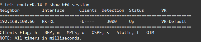
OK, so looking into this we can see that BFD is enabled on the RK-RL VLAN, and that it has subscribed a client in this case BGP to this BFD session.
Going a bit deeper by running: show bfd session detail, we see:
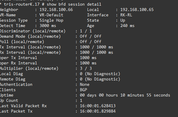
There are a few interesting things to mention in this output, you’ve obviously got the common things like the interface and neighbour IP addresses, but its some of the others.
Session Type
Single Hop in this case, because the two routers are directly connected, however if the BFD was flowing through one or more intermediate devices, this would become “multi-hop”.
Discriminator
The discriminator is an important part of BFD. A discriminator allows for the transmitting Router to identify each of the multiple BFD sessions which may be running on the same interface and or between the same pair of systems. Without this a transmitting Router would not be able to identify each of the BFD sessions it is sending, and additionally a receiving Router would not either.
- My Discriminator (MY_DISC or Local Discriminator) – A unique, non-zero discriminator value generated by the BFD sending router (Router K in the outputs above).
- Your Discriminator (YOUR_DISC or Remote Discriminator) – The discriminator received from the remote router, remote system (Router L in the outputs above). This field is the received value of My Discriminator (from the remote router, Router L in this example), or is zero if that value is unknown.
In our example the My Discriminator (MY_DISC or Local Discriminator) for Router K is set to 1, the Your Discriminator (YOUR_DISC or Remote Discriminator) of Router L is also set to 1 too. But this is not essential. They can be different, because the Your Discriminator (Remote Discriminator) is generated by the remote router, Router L in this instance and could be any random number.

Local Diag and Remote Diag
These are diagnostic codes that can give you an idea of the cause of any BFD failure. A diagnostic code specifying the local router’s reason for the last transition of the state from UP to DOWN or some other state.
- 0 – No Diagnostic
- 1 – Control Detection Time Expired
- 2- Echo Function Failed
- 3 – Neighbour Signalled Session Down
- 4 – Forwarding Plane Reset
- 5 – Path Down
- 6 – Concentrated Path Down
- 7 – Administratively Down
In our example we can see these are both showing 0 (for no diagnostic), if however I was to disable the port between Router K and Router L, this would read 7 (for administrative down).
Simulate a Failure – with BFD
Now we have BFD enabled, let’s see what happens during a failure, we’ll then repeat the test with BFD turned off, so you can see the difference.
We’ll shut down the link between Router K and Router L with: disable port 104.
Looking at Router L, we see the following immediately, the BFD Session is showing down, and the BGP Neighbour has transitioned to the IDLE state immediately, well within no more than 3 seconds or so.

Liven up the link again, and then we’ll test without BFD enabled.
Simulate a Failure – without BFD
We’ll first turn off BFD, remember you need to disable the BGP Neighbour (peer) configuration, then turn off BFD, then re-enable the BGP Neighbour again.
Router K
disable bgp neighbor 192.168.100.66
configure bgp neighbor 192.168.100.66 bfd off
enable bgp neighbor 192.168.100.66
Router L
disable bgp neighbor 192.168.100.65
configure bgp neighbor 192.168.100.65 bfd off
enable bgp neighbor 192.168.100.65
Verify
We’ll now re-run the test and disable the link between Router K and Router L, then see how long it takes now we don’t have BFD monitoring the link.
We’ll shut down the link between Router K and Router L with: disable port 104.

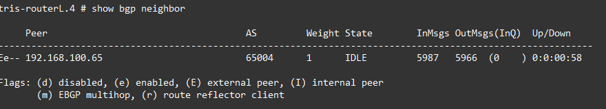
If we run a: show bgp neighbour 192.168.100.65 we see the following, the output has been cut to focus on the important bit(s):
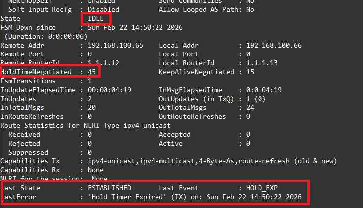
We had a stopwatch running, and it took just over 45 seconds for the BGP Neighbour to move the ESTABLISHED state to the IDLE state, during which Router K and Router L would both think that this was a valid and working path and would be attempting to send traffic down it. In our example we only have a single link between these two routers, but if there were multiple routes between these routers, or between the AS Red and AS Purple, then for that period of time connectivity would have been disrupted (for 45 seconds) until the network determined this path was no longer valid and re-routing traffic via a different route between the two networks, not ideal, therefore showing the value of BFD in these kinds of situations!
Examining the output above, specifically the bits highlighted in red, we can see the state “IDLE”, the Hold Timer being 45 seconds, hence why it determined the failure within about 45 seconds, rather than the default of 180 seconds! Then we have the state information, and we can see that the reason that the state changed was due to the “Hold Timer Expired”, which was obviously the case being that the link was down and three Keepalive messages would have been missed.
Before going any further, we’ll re-enable BFD on Router K and Router L, and bring the link back up and running.
Tweak Settings
You’ll notice that there are some settings that can be tweaked with regard to BFD, you adjust these on the VLAN, rather than the BGP Neighbour configuration, the output below shows you want kind of settings you can tweak.
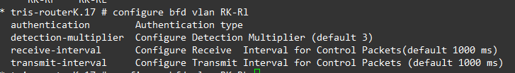
The authentication allows you to specify a password to be used for authentication of the BFD session, depending on your environment you may want this configured to ensure that your BFD session is set with who you expect it to be, especially useful when crossing an AS boundary, where you don’t have visibility or control over the other end of a link (also running BFD).
The other three are fairly self-explanatory, but these are the Receive Interval and Transmit Interval; so the rate at which the BFD packets are sent and expected to be received at, the default being 1000ms (1 second), the Detection Multiplier is the number of these Receive Intervals that can be missed before BFD decides that the link is down and notifies any subscribing protocols (such as BGP).
Its also worth mentioning BFD Hardware Assist (on Extreme Networks XOS), which allows for the BFD process to be offloaded to hardware, rather than operating in software; the benefit of this is that now you have the ability to shorten the intervals yet further (if you need to), to only a few milliseconds if required, which if you were attempting to do this without Hardware Assist, risks false positives due to the fluctuations of latency if/when the Router CPUs get busy.
You can read about this within this article: https://documentation.extremenetworks.com/exos_31.5/GUID-6199C8B8-66D1-4444-9AA6-E25BE918CB26.shtml
Once BFD has been enabled on the interfaces (and the routing protocols added) a BFD session is made, the BFD timers are negotated, and the BFD peers will begin to send BFD control packets to each other at whatever the negotiated interval is.
These appear to be bidirectional negotiations where the Highest Value Wins: If one router requests a minimum transmission interval of 100ms and the peer requests 1000ms, the BFD protocol negotiates the interval to the higher value (1000ms) to ensure both devices can handle the load.
Multi-Hop
Its worth noting about multi-hop. Although we don’t have the capability within the lab to test this (currently), BFD does not need to be enabled on only links that are directly connected to the receiving router.
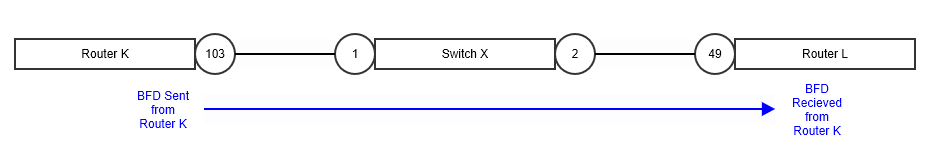
The example above shows how BFD, which uses BFD packets just flows across a link like any other, in just so happens that the link between these two Routers (Router K and Router L) flows via an intermediate switch (Switch X), in this configuration Switch X has nothing to do with the BGP, nor anything to do with the BFD session, it merely passes on the packets to Router L.
Router K and Router L have a BGP Neighbour (peering), which being that it flows via another switch in the middle, could have issues if say Switch X to Router L fails and stops passing traffic, but because Router K is unaware of this would have a period of time with no traffic flowing. BFD would detect the failure (nearly instantly), allow Router K (and Router L for that matter) to move the state the BGP Neighbour to INIT, and remove the routes from the BGP route table very rapidly.
Although in the example above, we’ve used a single VLAN, i.e. a single layer 2 segment between Router K and Router L, via Switch X, this is not essential, BFD packets can flow via routed interfaces and really is where the “multi-hop” nature of the configuration fits in, which is why it is important to configure on the Routers (at each end) if multi-hop is being used.
BFD packets are just normal UDP packets, 3784 (Single-Hop) / 4784 (Multi-Hop).
A key thing to remember is when using Multi-Hop BFD, you need to configure and use loopback IP addresses, which are what are used on the BFD session, not just interface IP addresses, which is typically what is used with single-hop BFD.
Conclusion
We’ve explored some simple examples of how BFD can be used to speed up how quickly BGP will detect if one of its neighbours has failed; the use of BFD on organisation networks has become almost essential nowadays especially when using BGP to ensure the network remains operational or gets back to operational as quickly as possible following a failure.
Additional Information
- https://documentation.extremenetworks.com/exos_30.2.2/GUID-9C466AC6-368E-472D-B00C-19657CFF1DC8.shtml
- https://extreme-networks.my.site.com/ExtrArticleDetail?an=000058478
- https://documentation.extremenetworks.com/exos_32.6.1/GUID-DB4570E0-934F-48C0-AD6E-9B5B6E053FAD.shtml
- https://extreme-networks.my.site.com/ExtrArticleDetail?an=000078861
- https://networklessons.com/cisco/ccie-routing-switching/bidirectional-forwarding-detection-bfd
- https://documentation.extremenetworks.com/exos_31.5/GUID-9C466AC6-368E-472D-B00C-19657CFF1DC8.shtml