Equal Cost Multi-Pathing (ECMP) is a mechanism where rather than finding the single best path and installing that into the route table, you instead install two (or more) equal best paths into the routing table; traffic then uses all of these best paths in a load balanced way using the switch’s hashing algorithm. For Extreme Networks XOS this appears to be: source/destination IP & source/destination L4 port number (https://extreme-networks.my.site.com/ExtrArticleDetail?an=000089944)
Normally with BGP the protocol will select a single best path for each prefix, and doesn’t do ECMP (Equal Cost Multi-pathing) by default; enabling ECMP allows you to load balance across two (or more) equal cost paths, take not of the “equal cost” this is important.
For BGP to be able to use the second path, the following BGP attributes have to match:
- Weight
- Local Preference
- AS Path (both AS number and AS path length)
- Origin code
- MED
- IGP metric
If they don’t match, they aren’t equal cost paths from BGP’s point of view!
Additionally, the next hop address (i.e. the next hop router) must be different, this comes into play when you have a router with two links (i.e. multihomed) like in our example below.
Topology Changes
We’ve added a new link between Router A Port 5 and Router C Port 5, which will provide redundant connectivity (paths) between these two routers. Sure they both go into the same Router, but in our case we want link resilience between AS Blue and AS Green and these two routers on top of the additional resilience we have via the link between Router C (and Router D).
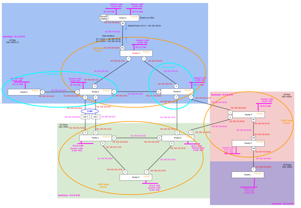
We physically add the additional link between Router A and Router C, then create a new point to point IP range for the new link with a new VLAN so it’s ready to become another BGP Neighbour (peering) for configuring ECMP.
Router A
Update the display strings and existing point to point VLAN name. Then create the new VLAN and its routed interface for the (new) second point to point link between Router A and Router C.
configure port 3 display-string "tris-RouterC-1"
configure vlan "RA-RC" name "RA-RC-1"
Then we can add the routed interface, enable OSPF passive interface (so the IGP within AS Blue 65001.0 advertises this range so it with be seen as a feasible route), then configure the BGP Neighbour peering to the remote side.
configure port 5 display-string "tris-RouterC-2"

create vlan "RA-RC-2"
configure vlan "RA-RC-2" ipaddress 192.168.100.69/30
enable ipforwarding vlan "RA-RC-2"
configure vlan "RA-RC-2" add port 5 untagged

configure ospf add vlan RA-RC-2 area 0.0.0.0 passive

create bgp neighbor 192.168.100.70 remote-AS-number 65002
configure bgp neighbor 192.168.100.70 source-interface ipaddress 192.168.100.69
enable bgp neighbor 192.168.100.70
configure bgp neighbor 192.168.100.70 send-community both
Router C
Update the display strings and existing point to point VLAN name. Then create the new VLAN and its routed interface for the (new) second point to point link between Router A and Router C.
configure port 3 display-string "tris-RouterA-1"
configure vlan "RC-RA" name "RC-RA-1"
Then we can add the routed interface, enable OSPF passive interface (so the IGP within AS Green 65002.0 advertises this range so it with be seen as a feasible route), then configure the BGP Neighbour peering to the remote side.
configure port 5 display-string "tris-RouterA-2"

create vlan "RC-RA-2"
configure vlan "RC-RA-2" ipaddress 192.168.100.70/30
enable ipforwarding vlan "RC-RA-2"
configure vlan "RC-RA-2" add port 5 untagged

configure ospf add vlan RC-RA-2 area 0.0.0.0 passive

create bgp neighbor 192.168.100.69 remote-AS-number 65001.0
configure bgp neighbor 192.168.100.69 source-interface ipaddress 192.168.100.70
enable bgp neighbor 192.168.100.69
Verify Connectivity
Now we need to check we can ping both ways across the new link from Router A to Router C and vice versa, pinging from the source address of that Router for the new link, hence:
Router A
ping 192.168.100.70 source 192.168.100.69And then:
Router C
ping 192.168.100.69 source 192.168.100.70Check Routing
Now we have the two links configured, with the BGP Neighbour peering in place between the two, we can now have a look at the Route Table on Router A and/or Router C so we can see what the behaviour is without ECMP being enabled; we’d be expecting that there is only one “best path” (route) for the various advertised network subnets between the two ASs.
Router A
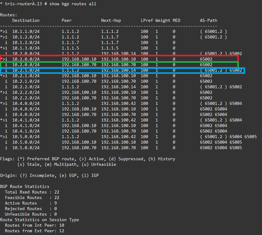
Now we have the second link enabled and working, we check the route table on Router A. We know that AS Blue has subnets within the supernet 10.2.0.0/16, and let’s pick just 10.2.0.0/24 and examine the routes we have for that network.
Shown circled in red is the active ( the best path/route) to 10.2.0.0/24 which is via 192.168.100.10 i.e. link 1 between Router A and Router C.
But we also have two more routes now. The one circled in green is an (inactive) route to 10.2.0.0/24 via 192.168.100.70 which is our new second link between Router A and Router C.
Finally, circled in blue we have another inactive route, which is probably least preferred, because it has a longer AS Path and that is a route that goes from Router A to Router B, then to Router D (in AS Blue).
Router C
We see the same thing, but in reverse obviously on Router C.

Let’s see what happens with these three routes for 10.2.0.0/24 when we turn on ECMP. If another one of those three are “equal” from a BGP point of view then they will become another best “active” path too.
Enable and Configure ECMP
We are now going to configure ECMP on Router A and Router C, we want to ensure that we load balance the return traffic too of course, it’s not 100% necessary though that the return traffic follow the same path back, as long as it is load balanced by ECMP to make best use of the links that we have available to us.
Note that BGP will need to be disabled on the router when you make this change, then re-enabled afterwards.
Router A
We run the following command to enable ECMP, just one line, that basically says you can have “2” best paths (for a network), rather than the default 1, that is assuming all the required attributes of each path are indeed the same.
configure bgp maximum-paths 2Router C
We run the following command to enable ECMP, just one line, that basically says you can have “2” best paths (for a network), rather than the default 1, that is assuming all the required attributes of each path are indeed the same.
configure bgp maximum-paths 2Verify
Now that we have ECMP enabled, we can then examine the Route Table to see how this has impacted the way the routes for the networks in AS Green and AS Blue are distributed between the two.
Router A
Now we have ECMP enabled when we review the route table on Router A what do we see? Well, we can now see the same three routes to 10.2.0.0/24 which we had before, but with a crucial difference.
Circled in red we can see that the route to 10.2.0.0/24 via 192.168.100.10 (link 1) is still the “best route” indicated by the asterisk, but we now have the route to 10.2.0.0/24 via 192.168.100.70 (link 2) is now also a “best route” as indicated by the “m” at the front.

So what this means is that depending on the hashing conducted by Router A, traffic going from AS Green (via Router A) to AS Blue, will now use both paths as indicated by the “m”.
Router C
When we examine the Router C side, what do we see?
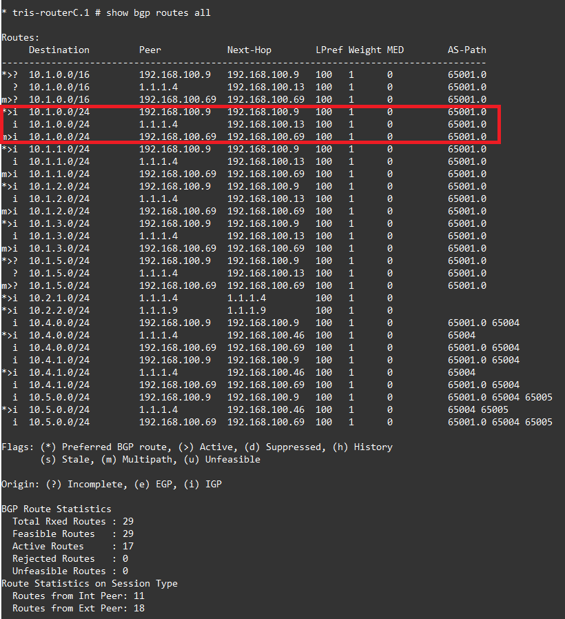
We see the same thing going back the other way so we have a second active “best” route for example 10.1.0.0/24 which is within AS Green.
Discussion
So now we have it working, let’s break it down. For ECMP to work the two routes need to have attributes that are exactly the same. Let’s work down the list and see!

So if we compare the bottom two routes i.e. the active ones that go via the next hops of 192.168.100.10 and 192.168.100.70:
- Weight = “1” for both so this matches.

- Local Preference = “100” for both so this matches
- AS Path (both AS Number and AS path length) = these are both “65002” so this matches
- Origin Code = The origin code which is the “i” at the front is the same both showing as IGP so this matches
- MED = The Multi-exit discriminator is the same on both the routes at 0, so this matches
- IGP Metric = The IGP Metric is a bit different, we need to check the main route table of the switch, and we see here the value of 1 for both, so that is also a match
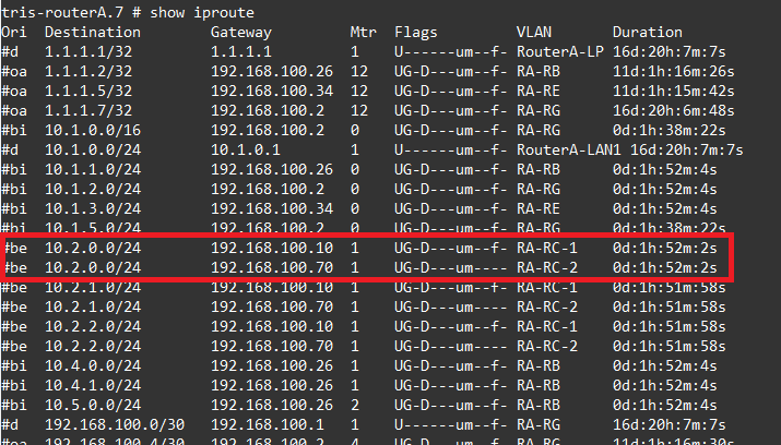
Which means the routes have the same ECMP attributes, and thus can both be installed as active “best” paths/routes for use by the routers at each end of the link.
Conclusion
We’ve explored the use of ECMP (Equal Cost Multi-pathing) that can be used to get the most out of your network and links at all times. It allows you to load balance traffic across links, rather than using a more active/backup type approach. Although in our example we have just used 2 links, depending on your network equipment manufacturer this could be 2, 3 or up to 8 links that are used within an ECMP to maximise the performance and availability of your network. ECMP more recently is commonly used within data centre networks between Leaf and Spine switches to maximise performance and minimise the effects of hardware or link failures.