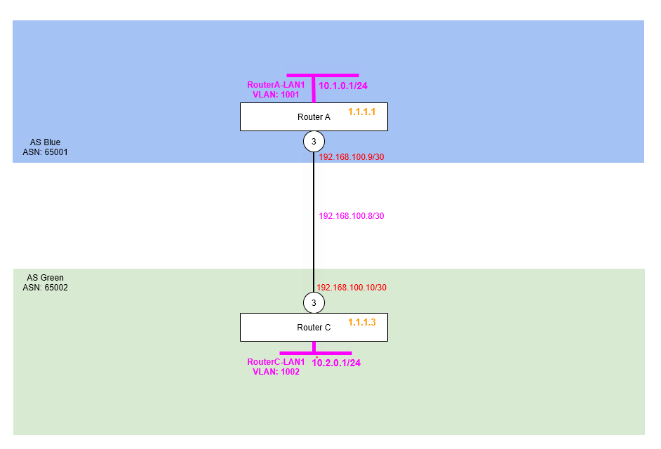
The first part is a basic deployment of BGP between two routers (Router A and Router B) with a single point to point link. In this example, each router is within its own AS (Autonomous System). Therefore any routes exchanged between each AS are eBGP (external BGP) routes. Routes exchanged within an AS are known as iBGP (internal BGP). For this first part we’re going to being using only eBGP (External BGP) because we’ll have two routers, each in its own AS.
Each Router has its own loopback configured (as a /32 network, 1.1.1.1 and 1.1.1.3 respectively), these are the same as the BGP RouterID for each router.
Always configure the Router ID to the IP address of a loopback interface for stability, as loopbacks don’t go down with physical links.
Step 1 – Configure Point to Point Links
Firstly, we are going to configure the point to point links between Router A and Router C.
Router A
create vlan "RA-RC"
configure vlan "RA-RC" ipaddress 192.168.100.9/30
enable ipforwarding vlan "RA-RC"
configure vlan "RA-RC" add port 3 untagged
Router C
create vlan "RC-RA"
configure vlan "RC-RA" ipaddress 192.168.100.10/30
enable ipforwarding vlan "RC-RA"
configure vlan "RC-RA" add port 3 untagged
Step 2 – Configure Loopback Interface for (Router ID)
We then need to add the loopback interfaces for each Router ID. Making this a loopback interface means it comes up and stays up, even there are no ports assigned or live in that VLAN.
Router A
create vlan "RouterA-LP"
configure vlan RouterA-LP tag 1111
enable loopback-mode vlan RouterA-LP
configure vlan RouterA-LP ipaddress 1.1.1.1 255.255.255.255
enable ipforwarding vlan RouterA-LP
Router C
create vlan "RouterC-LP"
configure vlan RouterC-LP tag 1113
enable loopback-mode vlan RouterC-LP
configure vlan RouterC-LP ipaddress 1.1.1.3 255.255.255.255
enable ipforwarding vlan RouterC-LP
Step 3 – Configure VLAN and Interface for Example LAN Networks (Subnets)
We’re going to create a couple of VLANs and interfaces on each Rotuer to be example LAN networks, i.e. default gateways, so we can use these for testing and more importantly as networks we’re advertising via BGP.
We’re enabling loopback on these for now, because they don’t have any ports assigned, but we want the network VLAN interface to be “up” so we can use it in testing.
So we’ll create a VLAN called RouterA-LAN1 (tag 1001) on Router A with the interface IP address of 10.0.1.1/24 (i.e. network subnet 10.0.1.0/24) and then another VLAN called RouterC-LAN1 (tag 1002) on Router C with the interface IP address of 10.0.2.1/24 (i.e. network subnet 10.0.2.0/24). We’ll then have something we can see and use for testing and proving what is going on!
Router A
create vlan "RouterA-LAN1" tag 1001
configure vlan "RouterA-LAN1" ipaddress 10.1.0.1/24
enable ipforwarding "RouterA-LAN1"
enable loopback-mode vlan "RouterA-LAN1"
Router C
create vlan "RouterC-LAN1" tag 1002
configure vlan "RouterC-LAN1" ipaddress 10.2.0.1/24
enable ipforwarding "RouterC-LAN1"
enable loopback-mode vlan "RouterC-LAN1"
Step 4 – Enable BGP and Create Neighbour
We are now going to enable BGP and create the BGP Neighbour between Router A and Router C. You’ll notice we are specifying the AS number of the routers, specifically Router A is going to be AS 65001 (Blue) and Router C will be in AS 65002 (Green). We’ll then specify the BGP Router ID, so we can identify this particular router and where routes have come from. Finally, we’ll specify the BGP Neighbour, which is configured by specifying the BGP Neighbour IP, in this case the other end of the point to point link along with the Remote AS Number, but then also the source interface IP address, so the local router knows which interface it should be making that BGP Neighbour with.
Note that we are not specifying any security here. You can if you wish add a shared secret here so that the BGP Neighbour can be authenticated somewhat.
Router A
configure bgp AS-number 65001
configure bgp routerid 1.1.1.1
enable bgp

create bgp neighbor 192.168.100.10 remote-AS-number 65002
configure bgp neighbor 192.168.100.10 source-interface ipaddress 192.168.100.9
enable bgp neighbor 192.168.100.10
Router C
configure bgp AS-number 65002
configure bgp routerid 1.1.1.3
enable bgp

create bgp neighbor 192.168.100.9 remote-AS-number 65001
configure bgp neighbor 192.168.100.9 source-interface ipaddress 192.168.100.10
enable bgp neighbor 192.168.100.9
Step 5 – Add Example LAN Network Subnet to BGP
We created example LAN network subnet on each router earlier, so we can actually advertise networks via BGP between the two routers; and exchange some routes between them. Due to the limitations of the test lab at this stage, we don’t have any downstream switches connected to the routers, so we don’t have something real, so instead we’ll create the VLAN interface, but then make it a loopback so the interface stays up artificially for testing purposes.
Once done, we’ll enable these networks for BGP, meaning that BGP will add these into the RIB.
Router A
configure bgp add network 10.1.0.0/24Router C
configure bgp add network 10.2.0.0/24At this point, we should be all set. The two routers should now exchange these routes via BGP, so Router A should be able to see a route to the 10.0.2.0/24 subnet and Router C a route to 10.0.1.0/24.
Step 6 – Verification and Testing
Before we dig into the route tables and the routes, let’s verify each of the parts one by one. We’ll do the same in future in later parts of this series when performing tests, but these won’t be written out in full like the below, so refer back to this section if you need to.
Verify Point to Point Link Status
From Router A and Router B respectively.
ping 192.168.100.10 from 192.168.100.9ping 192.168.100.9 from 192.168.100.10Verify “RouterA-LAN1” is Routable from Router C
ping 10.1.0.1 from 10.2.0.1As you can see the network, specifically the interface IP of the RouterA-LAN1 network is available when pinging from the RouterC-LAN1 interface.
Verify “RouterC-LAN1” is Routable from Router A
ping 10.2.0.1 from 10.1.0.1As you can see the network, specifically the interface IP of the RouterA-LAN1 network is available when pinging from the RouterA-LAN1 interface.
Inspect Routing Tables
We’ll look at the routing tables now on both sides to see what is what, as you can see the route is showing on Router A for Router C’s pretend LAN network and vice versa for Router C to Router A.
Notice how the route is showing as “be” meaning External BGP because the route is coming from another AS.
Router A
* tris-routerA.44 # show iproute
Ori  Destination        Gateway         Mtr  Flags         VLAN       Duration
#d   1.1.1.1/32         1.1.1.1         1    U------um--f- RouterA-LP 0d:0h:24m:42s
#d   10.1.0.0/24        10.1.0.1        1    U------um--f- RouterA-LAN1 0d:0h:23m:16s
#be  10.2.0.0/24        192.168.100.10  1    UG-D---um--f- RA-RC      0d:0h:6m:21s
#d   192.168.100.8/30   192.168.100.9   1    U------um--f- RA-RC      0d:0h:26m:32s

Origin(Ori): (b) BlackHole, (be) EBGP, (bg) BGP, (bi) IBGP, (bo) BOOTP
       (ct) CBT, (d) Direct, (df) DownIF, (dv) DVMRP, (e1) ISISL1Ext
       (e2) ISISL2Ext, (h) Hardcoded, (i) ICMP, (i1) ISISL1 (i2) ISISL2
       (is) ISIS, (mb) MBGP, (mbe) MBGPExt, (mbi) MBGPInter, (mp) MPLS Lsp
       (mo) MOSPF (o) OSPF, (o1) OSPFExt1, (o2) OSPFExt2
       (oa) OSPFIntra, (oe) OSPFAsExt, (or) OSPFInter, (pd) PIM-DM, (ps) PIM-SM
       (r) RIP, (ra) RtAdvrt, (s) Static, (sv) SLB_VIP, (un) UnKnown
       (*) Preferred unicast route (@) Preferred multicast route
       (#) Preferred unicast and multicast route

Flags: (B) BlackHole, (b) BFD protection requested, (c) Compressed, (D) Dynamic
       (f) Provided to FIB, (G) Gateway, (H) Host Route, (L) Matching LDP LSP
       (l) Calculated LDP LSP, (3) L3VPN Route, (m) Multicast, (P) LPM-routing
       (p) BFD protection active, (R) Modified, (S) Static, (s) Static LSP
       (T) Matching RSVP-TE LSP, (t) Calculated RSVP-TE LSP, (u) Unicast, (U) Up

MPLS Label: (S) Bottom of Label Stack
Mask distribution:
     2 routes at length 24           1 routes at length 30
     1 routes at length 32

Route Origin distribution:
     3 routes from Direct               1 routes from EBGP


Total number of routes = 4
Total number of compressed routes = 0
Router C
* tris-routerC.46 # show iproute
Ori  Destination        Gateway         Mtr  Flags         VLAN       Duration
#d   1.1.1.3/32         1.1.1.3         1    U------um--f- RouterC-LP 0d:0h:23m:3s
#be  10.1.0.0/24        192.168.100.9   1    UG-D---um--f- RC-RA      0d:0h:5m:11s
#d   10.2.0.0/24        10.2.0.1        1    U------um--f- RouterC-LAN1 0d:0h:21m:29s
#d   192.168.100.8/30   192.168.100.10  1    U------um--f- RC-RA      0d:0h:24m:48s

Origin(Ori): (b) BlackHole, (be) EBGP, (bg) BGP, (bi) IBGP, (bo) BOOTP,
       (ct) CBT, (d) Direct, (df) DownIF, (dv) DVMRP, (e1) ISISL1Ext,
       (e2) ISISL2Ext, (h) Hardcoded, (i) ICMP, (i1) ISISL1 (i2) ISISL2,
       (is) ISIS, (mb) MBGP, (mbe) MBGPExt, (mbi) MBGPInter, (mp) MPLS Lsp,
       (mo) MOSPF (o) OSPF, (o1) OSPFExt1, (o2) OSPFExt2,
       (oa) OSPFIntra, (oe) OSPFAsExt, (or) OSPFInter, (pd) PIM-DM, (ps) PIM-SM,
       (r) RIP, (ra) RtAdvrt, (s) Static, (sv) SLB_VIP, (un) UnKnown,
       (*) Preferred unicast route (@) Preferred multicast route,
       (#) Preferred unicast and multicast route.

Flags: (b) BFD protection requested, (B) BlackHole, (c) Compressed, (D) Dynamic,
       (f) Provided to FIB, (G) Gateway, (H) Host Route, (l) Calculated LDP LSP,
       (L) Matching LDP LSP, (m) Multicast, (p) BFD protection active, (P) LPM-routing,
       (R) Modified, (s) Static LSP, (S) Static, (t) Calculated RSVP-TE LSP,
       (T) Matching RSVP-TE LSP, (u) Unicast, (U) Up, (3) L3VPN Route.

MPLS Label: (S) Bottom of Label Stack
Mask distribution:
     2 routes at length 24           1 routes at length 30
     1 routes at length 32

Route Origin distribution:
     3 routes from Direct               1 routes from EBGP


Total number of routes = 4
Total number of compressed routes = 0
Down Link – Verify Behaviour
To prove the routes are being advertised, let’s down the link between the two.
When we repeat the ping test from Router A to Router C’s network it now fails!
Let’s examine the route table on Router A.
* tris-routerA.2 # show iproute
Ori  Destination        Gateway         Mtr  Flags         VLAN       Duration
#d   1.1.1.1/32         1.1.1.1         1    U------um--f- RouterA-LP 0d:0h:32m:14s
#d   10.1.0.0/24        10.1.0.1        1    U------um--f- RouterA-LAN1 0d:0h:30m:48s
 d   192.168.100.8/30   192.168.100.9   1    -------um---- RA-RC      0d:0h:34m:4s

Origin(Ori): (b) BlackHole, (be) EBGP, (bg) BGP, (bi) IBGP, (bo) BOOTP
       (ct) CBT, (d) Direct, (df) DownIF, (dv) DVMRP, (e1) ISISL1Ext
       (e2) ISISL2Ext, (h) Hardcoded, (i) ICMP, (i1) ISISL1 (i2) ISISL2
       (is) ISIS, (mb) MBGP, (mbe) MBGPExt, (mbi) MBGPInter, (mp) MPLS Lsp
       (mo) MOSPF (o) OSPF, (o1) OSPFExt1, (o2) OSPFExt2
       (oa) OSPFIntra, (oe) OSPFAsExt, (or) OSPFInter, (pd) PIM-DM, (ps) PIM-SM
       (r) RIP, (ra) RtAdvrt, (s) Static, (sv) SLB_VIP, (un) UnKnown
       (*) Preferred unicast route (@) Preferred multicast route
       (#) Preferred unicast and multicast route

Flags: (B) BlackHole, (b) BFD protection requested, (c) Compressed, (D) Dynamic
       (f) Provided to FIB, (G) Gateway, (H) Host Route, (L) Matching LDP LSP
       (l) Calculated LDP LSP, (3) L3VPN Route, (m) Multicast, (P) LPM-routing
       (p) BFD protection active, (R) Modified, (S) Static, (s) Static LSP
       (T) Matching RSVP-TE LSP, (t) Calculated RSVP-TE LSP, (u) Unicast, (U) Up

MPLS Label: (S) Bottom of Label Stack
Mask distribution:
     1 routes at length 24           1 routes at length 30
     1 routes at length 32

Route Origin distribution:
     3 routes from Direct

Total number of routes = 3
Total number of compressed routes = 0
And also the BGP Neighbours (Router C) on Router A.
* tris-routerA.6 # show bgp neighbor

     Peer            AS         Weight State        InMsgs OutMsgs(InQ)  Up/Down
-----------------------------------------------------------------------------------
Ee-- 192.168.100.10  65002      1      ACTIVE       28     33    (0    ) 0:0:00:18

Flags: (d) disabled, (e) enabled, (E) external peer, (I) internal peer
       (m) EBGP multihop, (r) route reflector client

BGP Peer Statistics
  Total Peers       : 1
  EBGP Peers        : 1                 IBGP Peers          : 0
  RR Client         : 0                 EBGP Multihop       : 0
  Enabled           : 1                 Disabled            : 0
Inspect the route tables on each router, as you can see the routes for our two networks RouterA-LAN1 and RouterC-LAN1 are no where to be seen when examining each router. On Router A we’d expect to be seeing the route for 10.0.2.0/24 within the route table, but because the link between the two routers is down, we can’t!
Conclusion
Although this is a simple example for the first BGP Test Lab part 1, it gives an overview of the basics of route exchange between BGP Autonomous Systems. In the next part we’ll explore further into BGP where we’ll build up the complexity of the test lab environment and begin to go into a more elaborate and more complicated configuration.
1 thought on “BGP Test Lab – Part 1 – Introduction and Basic Two Router Configuration”