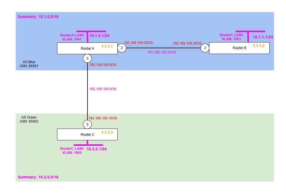
Internal BGP (iBGP) is the next part of our deployment. We are going to be deploying two routers within one of the AS, Blue 65001. Remember that eBGP is used between AS and iBGP is used within an AS. So in this case our second router, Router B, will be linked to Router A via a single link, these two Routers will exchange routes using iBGP and Router A will act as the bridgehead that exchanges routes out to Router C within the other AS Green 65002.
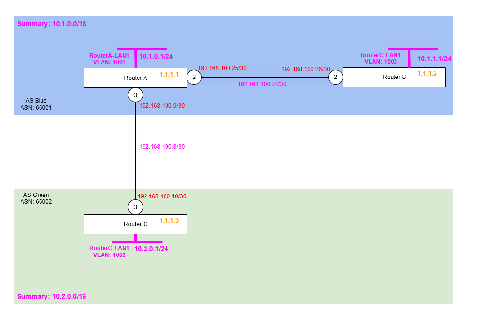
You’ll notice on the diagram below, the summary supernet has been added, although not essential, it’s good to be able to summarise whole ranges of address space to minimise the number of routes being exchanged. In this case AS Blue 65001 is having the summary 10.1.0.0/16, while AS Green 65002 is having 65002.
Another very important thing to know is that iBGP requires (caveat below), a “full mesh” between all Routers within the AS. i.e. each Router within an AS must have a direct link to every other one, in this case we have two Router A and Router B, so we are fine. But if we were to add another Router to this AS, this would need links to both Router A and Router B too.
However, you can also use iBGP without a “full mesh”, we’ll explore the techniques for how, when and why in later parts of this series, such as: using another routing protocol to exchange routes, Route Reflector and Confederations.
If you’ve not read BGP Test Lab – Part 1 – Introduction and Basic Two Router Configuration do that now, because this configuration builds upon this.
The example assumes that you have two Routers already powered on, cabled up and ready for configuration.
Step 1 – Configure Point to Point Links
First step is to configure the point to point links between Router A and Router C.
Router A
We add the point to point IP and VLAN for this link, ensuring it is enabled for routing.
create vlan "RA-RB"
configure vlan "RA-RB" ipaddress 192.168.100.25/30
enable ipforwarding vlan "RA-RB"
configure vlan "RA-RB" add port 2 untagged
Router B
We add the point to point IP and VLAN for this link, ensuring it is enabled for routing.
create vlan "RB-RA"
configure vlan "RB-RA" ipaddress 192.168.100.26/30
enable ipforwarding vlan "RB-RA"
configure vlan "RB-RA" add port 2 untagged
You should now be able to ping from the interface IP on Router B to the interface IP on Router A for this newly added link, if you cannot verify your configuration before proceeding further.
Step 2 – Configure Loopback Interface for Router ID
We then need to add the loopback interfaces for the Router ID on Router B.
Router B
Making this a loopback interface means it comes up and stays up, even there are no ports assigned or live in that VLAN.
create vlan "RouterB-LP"
configure vlan RouterB-LP tag 1112
enable loopback-mode vlan RouterB-LP
configure vlan RouterB-LP ipaddress 1.1.1.2 255.255.255.255
enable ipforwarding vlan RouterB-LP
Step 3 – Configure VLAN and Interface for Example LAN (Subnet) on Router B
We’re going to create a VLAN and interface on Router B to be example LAN network, i.e. default gateway, so we can use these for testing and more importantly as networks we’re advertising via BGP.
We’re enabling loopback on this for now, because it doesn’t have any active ports in the VLAN to keep it up, but it needs to be up for us to use it for testing.
Router B
So we’ll create a VLAN called RouterB-LAN1 (tag 1003) on Router B with the interface IP address of 10.1.1.1/24 (i.e. network subnet 10.1.1.0/24), all within the summarised network of 10.1.0.0/16. We used 10.1.0.0/24 for the RouterA-LAN1 subnet which is connected to Router A.
create vlan "RouterB-LAN1" tag 1003
configure vlan "RouterB-LAN1" ipaddress 10.1.1.1/24
enable ipforwarding "RouterB-LAN1"
enable loopback-mode vlan "RouterB-LAN1"
Step 4 – Enable BGP and Create Neighbour
Okay, now we are ready to enable BGP on Router B, but we’re also going to need to do some configuration on Router A too. Firstly, on Router B we’ll need to enable BGP and configure it’s AS number (same as Router A because its in the same AS) and a Router ID too. Then, we’ll configure the BGP Neighbour to Router A, the configuration for this is a bit different to what we did in the first part being this is iBGP rather than eBGP.
Router B
We enable BGP, then we add the neighbour with Router A.
configure bgp AS-number 65001
configure bgp routerid 1.1.1.2
enable bgp

create bgp neighbor 192.168.100.25 remote-AS-number 65001
configure bgp neighbor 192.168.100.25 source-interface ipaddress 192.168.100.26
enable bgp neighbor 192.168.100.25
Router A
We don’t need to set up BGP, that was already done, we just need to add the BGP Neighbour to Router C.
create bgp neighbor 192.168.100.26 remote-AS-number 65001
configure bgp neighbor 192.168.100.26 source-interface ipaddress 192.168.100.25
enable bgp neighbor 192.168.100.26
Verify
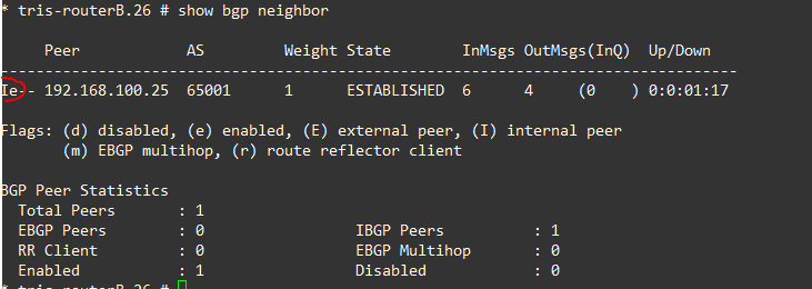
Before going any further ensure that you can see the BGP Neighbour adjacency within the output of the “show bgp neighbor” command, the neighbour is showing as state “ESTABLISHED” and that the router is showing as an “internal peer”, i.e. iBGP which can be seen by the “I” at the beginning for example:
Step 5 – Add Example LAN Subnet to BGP
In Step 2, we added an example LAN that we could use for testing, so we can actually advertise networks via BGP between the routers; and exchange some routes between them. Due to the limitations of the test lab at this stage, we don’t have any downstream switches connected to the routers, so we don’t have something real, so instead we’ll create the VLAN interface, but then make it a loopback, so the interface stays up artificially for testing purposes.
Once done, we’ll enable this for BGP, meaning that BGP will add these into the RIB.
Router B
We add the subnet that we want to have advertised.
configure bgp add network 10.1.1.0/24Step 6 – Verify iBGP Usage, Route Exchange and Troubleshooting
Now the configuration is done, we can verify what is happening.
Question 1: Is iBGP being used to advertise the routes within the AS?
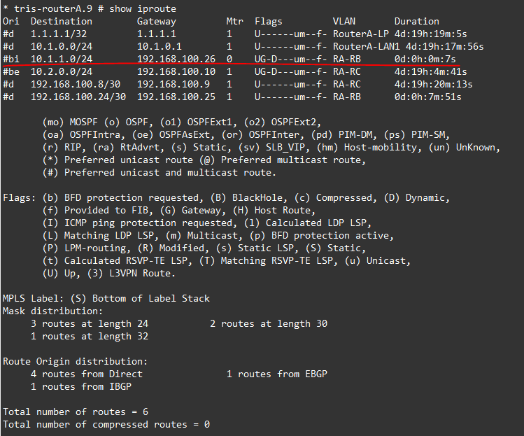
To determine this we run the command “show iproute” and “show bgp neighbor” from Router A and Router C, and we can indeed see that on Router A, the RouterB-LAN1 subnet (10.1.1.0/24) is being advertised via iBGP to Router A and on Router B we can see that Router A’s RouterA-LAN1 subnet (10.1.0.0/24) is being advertised via iBGP to Router A.

Based on these outputs, we can see that the iBGP is being used to exchange the routes within the AS.
Question 2: Is the route learned from Router B being advertised to Router C? And vice versa?
For all the traffic to flow between all three of our LAN subnets, all three routers need to know a route to all three of the networks, so that outgoing traffic knows where to go, but equally as important the return traffic knows it’s way back!
Investigation
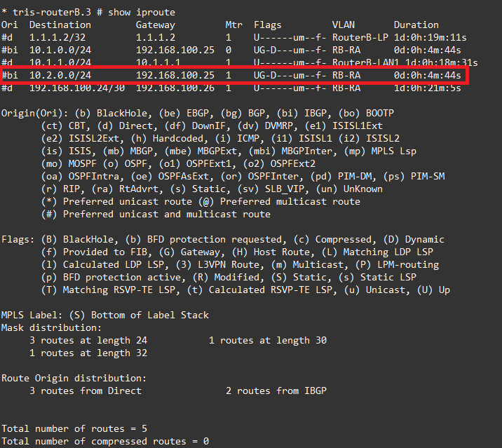
Let’s examine Router C’s route table, that all looks fine, the circled routes are those from AS Blue 65001, and we can see we have both the LANs being advertised.
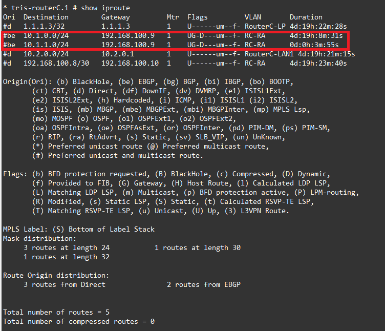
Router A shows what we would expect, the LAN subnet from AS Green 65002 and the LAN subnet from its local interface 10.1.0.0/24 as well as the route from Router C within the same AS.

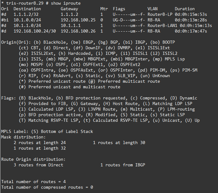
Now we come to Router B and this is where we have a problem. Notice that the Router C LAN is missing. What this means is, that although a client on the RouterC-LAN1 (10.2.0.0/24) might be able to reach the RouterB-LAN1 (10.1.1.0/24), Router B has no route back to this VLAN, so connectivity won’t work.
Cause
So why is this happening? Why is Router B not learning the route from Router A via iBGP?
It’s all down to the differences between eBGP and iBGP. Every BGP route has a NEXT_HOP attribute: “If you want to reach this prefix, send packets to this IP address.”
So with eBGP when a router leans a route via eBGP, it changes the NEXT_HOP to itself when advertising the route onward (to downstream routers). But when iBGP learns a route it does not change NEXT_HOP when advertising the route onward (to downstream routers). What this means we can now see in the outputs below.
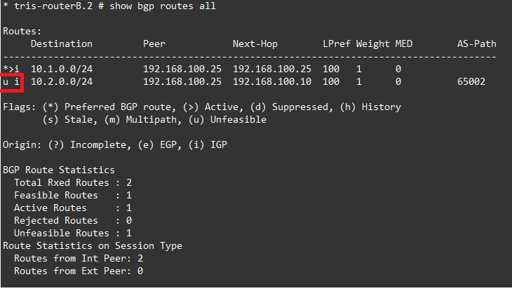
The outputs are from Router B, we can see here that Router B has indeed learnt the route for Router C’s LAN RouterC-LAN1 (10.2.0.0/24), but notice that there is a “u” for unfeasible next to this route. Because of this although the route has been learnt by the Router B, it’s not been added to the routing table of Router B, ergo, if you were to try to ping from the interface of RouterB-LAN1 (i.e. 10.1.1.1) to the interface of RouterC-LAN1 (i.e. 10.2.0.1) (or vice versa) then you’d find it didn’t work!

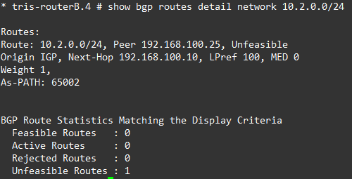
Notice the “Next-Hop 192.168.100.10” value for the route to this network 10.2.0.0/24 in the second output (right). From Router B’s point of view, it doesn’t have a route to 192.168.100.10, this IP is on Router A (and Router A is the only router in AS Blue that knows about it), therefore Router B can’t send any traffic to it (directly), which therefore makes this route unfeasible from Router B’s point of view.
So we now know what is happening and why this route is not being added to Router B’s route table (because its unfeasible), the question is how do we go about fixing this, and what are the right ways and wrong ways to do this?
There are a few ways that can be implemented, we’ll explore the first in the section below called: “Step 7 – Configure iBGP Next-Hop for Edge Router (Bridgehead Router)”, and the others in subsequent parts of this series.
Step 7 – Configure iBGP Next-Hop for Edge Router (Bridgehead Router)
There is the concept of the “Next-Hop-Self” configuration. What “Next-Hop-Self” does is to tell a router, for example Router A in this example (i.e. the edge/bridgehead router) to re-write the route’s NEXT_HOP attribute with itself when advertising on iBGP routes. i.e. to behave like eBGP effectively.
Why?
OK, so if it’s that easy, what’s the big deal. Well, the “Next-Hop-Self” is not the fix, well not the fix for all eventualities, it is a reasonable way to resolve this issue in certain configurations.
Now in our case we have the following topology, Router A is the edge router (or bridgehead router) for the AS Blue 65001, and Router B is an internal router. Therefore, setting “next-hop-self” on the routes being advertised from Router A to router B is reasonable, because Router B essentially has nowhere else to go being it is a “router on a stick” type configuration.
In this case us manipulating the routes as they are advertised across is okay, we’re not doing anything particularly problematic for ourselves. But if in future the network (within AS Blue) were to grow, it’s a design decision that would need to be revisited.
Why Not?
Using next-hop-self is not a magic solution, but can work well in certain situations. So why should you not use it?
Next-hop-self can, if used in the wrong situation:
- cause issues by breaking the way that you’d expect BGP to work, this can mean that traffic flows in unexpected ways, or ways not designed for.
- cause an AS with multiple exit points to hide these exit points, meaning reduction in availability in the event of failure or traffic not flowing out of multiple exit points as expected.
- at best cause suboptimal routing and traffic flows and at worst loss of connectivity in certain (failure) scenarios.
Options
So what are the options?
- Next-Hop-Self – As described above, we set the BGP neighbour configuration to use “next-hop-self” on Router A, so any routes it learns (from Router C) have the NEXT_HOP attribute changed to Router A as the next hop, essentially to the IP address at the other end of the point to point IP from Router C’s point of view.
- Inject Next-Hop Subnets into another routing protocol – Using another routing protocol (interior routing protocol) for example OSPF or EIGRP etc., we distribute all the routes for the “next-hop” subnets, i.e. the point to point links via another routing protocol. So in this example Router C would learn the route to 192.168.100.9/30 (i.e. 192.168.100.10) but not via BGP it would learn it say via OSPF. Router C would therefore find that previously unfeasible route is now feasible and it would appear in the route table and connectivity would work.
- Route Reflectors – A more scalable approach is to use Route Reflectors to distribute the routes effectively within an AS.
But What About Loops?
It’s possible for routing loops to occur. BGP has mechanisms to avoid these happening, and these differ based on if you are using iBGP or using eBGP.
- eBGP prevents loops using the AS_PATH: if you ever see your own AS number in the path of a route, you reject the route and don’t install it in that router’s routing table, therefore no loop can form.
- iBGP cannot use AS_PATH for loop prevention (because all routers are in the same AS), so it uses strict propagation rules instead: routes learned from iBGP are not re-advertised to other iBGP peers. Therefore, there no loop can form via this method.
For eBGP this is very simple and effective. But requires that routes go across AS, so they can appear in the AS_PATH.
But for iBGP this is not the case, there is only one AS, so routes that are propagated don’t have an AS added to AS_PATH, being it is in the same one. For example:
R1 —— R2 —— R3- R1 advertises a route to R2 (iBGP)
- R2 cannot advertise it to R3
- Therefore, the route cannot circulate indefinitely
This is loop prevention by suppression, not detection.
The cost of this rule therefore is that:
- iBGP does not scale naturally
- And to scale requires techniques like:
- Full mesh, or
- Route reflectors, or
- Confederations
Resolution – Using Next-Hop-Self
Okay, so enough about the theory, let’s get this fixed and working again.
All we need to do is edit the BGP neighbour configuration on Router A to ensure the neighbour to Router C is marked as “next-hop-self”.
Router A
disable bgp neighbor 192.168.100.26
configure bgp neighbor 192.168.100.26 next-hop-self
enable bgp neighbor 192.168.100.26
Okay, that should do it. The BGP routes that Router A has learnt will be advertised to Router C, but with the NEXT_HOP attribute set to the Router A end of the point to point link, i.e. 192.168.100.25. We’ll verify this in the final step.
Step 8 – Verify Behaviour
So we should be good to go now, so let’s verify this:
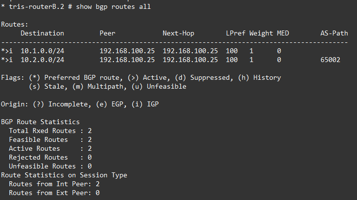
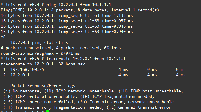
As we can see Router B is now seeing 10.2.0.0/24 which is the RouterC-LAN1 network subnet being installed as a route in the route table.
And the ping and traceroute now work as expected.