In the previous article we discovered that iBGP requires a topology and usage that ensures that our exchange of routes between routers is not stopped by the iBGP rule: “A route learned via iBGP must not be advertised to another iBGP peer.” We came across this problem in the previous article where although in normal operational the routes were being sent as expected, if there was a loss of a link between Router A and (the newly added) Router G, the surviving link Router G had to Router B would not receive the routes from Router B (which Router B had learnt).
Essentially when the term “full mesh” is used this is actually a logical concept not a physical concept.
A router using iBGP must have a “full mesh” to every other iBGP router, however, it does not mean you need physical links to every other Router; it just means that every iBGP Router must have a BGP Neighbour (peer) with every other one (in the AS).
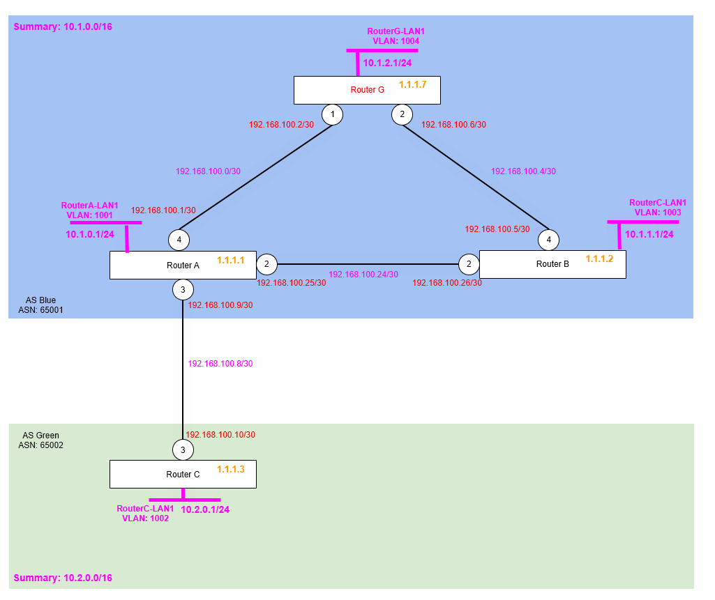
So the physical topology isn’t changing from what we had in the previous article, but we will now be reconfiguring the enivronment within the AS Blue 65001 Autoonmous System.
Once re-configured we’ll be able to ensure the correct exchange of routes via iBGP, is being supported by another interior routing protocol (OSPF in this case) that will exchange routes for the Router’s loopback addresses in a full (flooded) way, so that loss of physical links (e.g. failure) won’t mean we end up with a non-meshed topology which was the case in the previous articile’s topology.
By use of another interior routing protocol to take care of the underlying routes needed for iBGP work as expected, we can ensure that the BGP Neighbour (peering) adjencies are persisted (unless of course a router fails or is completely isolated, i.e. both redundant links fail at once).
Step 1 – Remove Problematic BGP Neighbour (Peer) Configuration
Based on what we learnt in the last article, we need to remove our BGP neighbour configuration, add the necessary OSPF (IGP protocol) configuration to distribute the each Router’s Loopback IP Address, and then finally re-add the BGP Neighbours, however this time specifying the neighbours to use the Router’s Loopback IP addres, rather than a point to point IP Address.
We of course want to leave the Router A to Router B BGP Neighbour in place, i.e. the one that links Router A and Router C between the two Autonomous Systems (AS).
Router A
disable bgp neighbor 192.168.100.2
disable bgp neighbor 192.168.100.26

delete bgp neighbor 192.168.100.2
delete bgp neighbor 192.168.100.26
Router B
disable bgp neighbor 192.168.100.6
disable bgp neighbor 192.168.100.25

delete bgp neighbor 192.168.100.6
delete bgp neighbor 192.168.100.25
Router G
disable bgp neighbor 192.168.100.1
disable bgp neighbor 192.168.100.5

delete bgp neighbor 192.168.100.1
delete bgp neighbor 192.168.100.5
Now all the old BGP Neighbour configuration has been removed, we are ready to configure the OSPF.
Step 2 – Enable and Configure OSPF
So now we need to enable our IGP (Interior Gateway Protocol), i.e. the supporting routing protocol that will deal with the physically topology (links) between the routers, so that iBGP can be used on-top form a “full mesh” and work as iBGP is intended to be used. Let’s get to it.
We’ll enable OSPF on each router within the Autonomous System, AS Blue and we then only need to enable OSPF on the links between the Routers within the AS, we don’t need to enable OSPF outside of our AS, that’s where BGP (eBGP) will be exchanging the routes!
Note that we are not setting any particular priority on OSPF, being these are point to point OSPF links, there is no DR/BDR elected (link), so they’ll just show as DROTHER.
Once OSPF is enabled, we then tell it to advertise the Router ID, in our case which is also a Loopback IP Address into OSPF; and it is this which we will use with BGP to configure the BGP Neighbours. The loopback interfaces are advertised as OSPF passive, because we won’t have OSPF adjacencies forming with the actual loopback IP addresses.
Router A
configure ospf routerid 1.1.1.1
enable ospf

configure ospf add vlan RA-RB area 0.0.0.0 link-type point-to-point

configure ospf add vlan RA-RG area 0.0.0.0 link-type point-to-point

configure ospf add vlan RouterA-LP area 0.0.0.0 passive
Router B
configure ospf routerid 1.1.1.2
enable ospf

configure ospf add vlan RB-RA area 0.0.0.0 link-type point-to-point

configure ospf add vlan RB-RG area 0.0.0.0 link-type point-to-point

configure ospf add vlan RouterB-LP area 0.0.0.0 passive
Router G
configure ospf routerid 1.1.1.7
enable ospf

configure ospf add vlan RG-RA area 0.0.0.0 link-type point-to-point

configure ospf add vlan RG-RB area 0.0.0.0 link-type point-to-point

configure ospf add vlan RouterG-LP area 0.0.0.0 passive
Verify
So before we go any further, let’s verify the Route Tables on each of the Routers A, B and G. What we want to ensure is that each of the Router ID (Loopback IP Addresses) of each router are being learned by each of the other Routers in the AS. Just Router A is shown below:

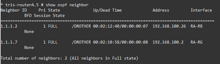
We can also verify we have two OSPF adjancencies on each Router, here’s what Router A sees:
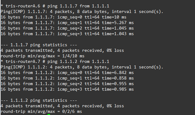
We should also be able to ping from each Router’s Loopback IP Address, to another Router’s Loopback IP address, as shown below, Router A can reach Router B and Router G’s loopback IP addresses OK based on the routes it has learnt via OSPF.
Break-it and Verify
We now need to check that even if a link between one of the three routers were to go down, that the connectivity between the loopbacks is preserved. As we’ve learnt earlier (in previous articles), this “full mesh” must be maintained or otherwise routes learnt via iBGP will be incomplete due to the rule: “A route learned via iBGP must not be advertised to another iBGP peer”.
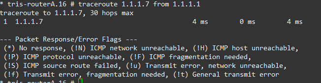
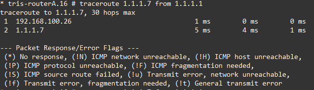
If we down the link between Router A and Router G, then attempt to ping/traceroute from Router A’s Loopback IP (1.1.1.1) to Router G’s Loopback IP (1.1.1.7), we can observe that connectivity is maintained and the route changes accordingly based on what OSPF is advertising.
Left is before downing the link, right is after downing the link.
We re-enable the port and that confirms that all looks good, we can now progress to configuring BGP again.
Step 3 – Reconfigure BGP to Use Router Loopback Addresses for BGP Neighbour
We have now the underlying IGP (Interior Gateway Protocol), in this case OSPF in place and working, so now we can reconfigure BGP so that it will form a “full mesh” between each Router’s Loopback interface.
Router A
create bgp neighbor 1.1.1.2 remote-AS-number 65001
configure bgp neighbor 1.1.1.2 source-interface ipaddress 1.1.1.1
enable bgp neighbor 1.1.1.2

create bgp neighbor 1.1.1.7 remote-AS-number 65001
configure bgp neighbor 1.1.1.7 source-interface ipaddress 1.1.1.1
enable bgp neighbor 1.1.1.7
Router B
create bgp neighbor 1.1.1.1 remote-AS-number 65001
configure bgp neighbor 1.1.1.1 source-interface ipaddress 1.1.1.2
enable bgp neighbor 1.1.1.1

create bgp neighbor 1.1.1.7 remote-AS-number 65001
configure bgp neighbor 1.1.1.7 source-interface ipaddress 1.1.1.2
enable bgp neighbor 1.1.1.7
Router G
create bgp neighbor 1.1.1.1 remote-AS-number 65001
configure bgp neighbor 1.1.1.1 source-interface ipaddress 1.1.1.7
enable bgp neighbor 1.1.1.1

create bgp neighbor 1.1.1.2 remote-AS-number 65001
configure bgp neighbor 1.1.1.2 source-interface ipaddress 1.1.1.7
enable bgp neighbor 1.1.1.2
With this BGP configuration, iBGP never needs to “re-advertise” anything, because there is a full mesh all of the time, being that the BGP neighbours are between the Router’s Router ID not some physical link, meaning the only situation there isn’t a “full mesh” is when a Router were to fail or all its redundant links were to fail simulatnoeously; at which point there is still a “full mesh” of all the surviving (still running) routers!
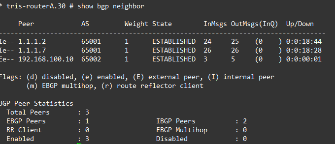
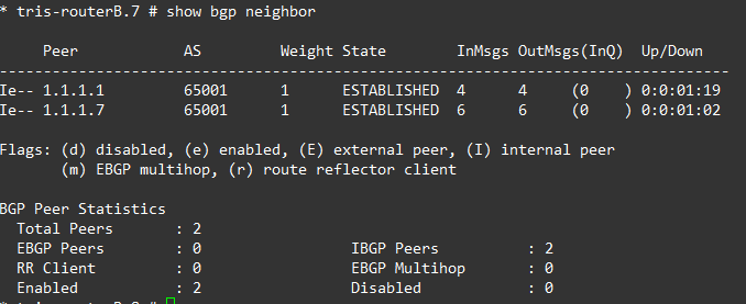
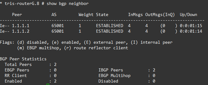
Ergo, Router A has BGP neighbours of all the routers within the AS: Router B and Router G. And Router B and Router G the same respectively.
If we examine each router’s BGP Neighbours, everything is established and showing as iBGP peers as we’d expect.
Step 4 – Verify
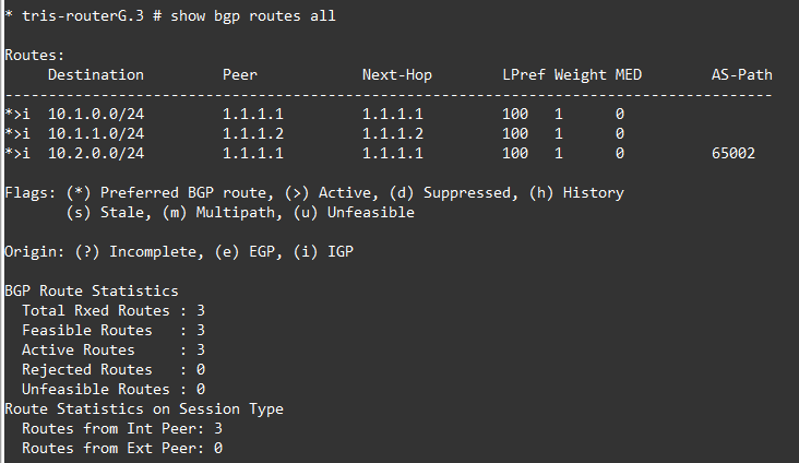
Now we can move onto examining the actual routes. So let’s do that, below are the three BGP Routes for Router A, Router B and Router G.
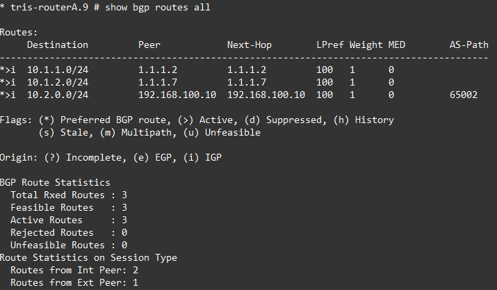
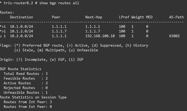

Oh dear, what can we see?
Router A is fine, but Router B and Router G are not able to install the route for Router C’s LAN RouterC-LAN 10.2.0.0/24 because the NEXT_HOP attribute is for the point to point link between Router A and Router C for which they do not have a route, i.e. no route to 192.168.100.8/30.
So how can this be fixed? There’s a few options available to us, but let’s discuss and try these two:
1. Next-Hop-Self
2. Add RouterA→RouterC point to point link subnet to OSPF
Option 1 – Next-Hop-Self
Make the Router A to Router B, and the Router A to Router G BGP neighbour peerings use “Next-hop-self”.
Router A
disable bgp neighbor 1.1.1.2
configure bgp neighbor 1.1.1.2 next-hop-self
enable bgp neighbor 1.1.1.2

disable bgp neighbor 1.1.1.7
configure bgp neighbor 1.1.1.7 next-hop-self
enable bgp neighbor 1.1.1.7
Verify
Now let’s verify what is going on by looking at the actual routes from the three routers: A, B and G.
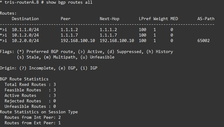
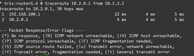
OK, so that now looks better for Router B and G. The route has been installed successfully, which is what we want. Tests show that we can reach Router C’s LAN network (10.2.0.1) from Router G’s LAN network (10.1.2.1).
Option 2 – Add RouterA→RouterC point to point link subnet to OSPF
Another option is instead of using next-hop-self, which can in certain situations become problemtatic, we could advertise the Router A to Router C point to point link (network) into OSPF.
The issue we were seeing on Router B and G was they were never installing the route for 10.2.0.0/24 (from Router C), hence it was showing as “unfeasible”, because they had no route to the “next-hop”, i.e. the Router A to Router C point to point network (192.168.100.8/30).
Let’s try to fix that now.
But first, we need to remove the “next-hop-self” configuration from Router A, so run the following on Router A:
disable bgp neighbor 1.1.1.2
configure bgp neighbor 1.1.1.2 no-next-hop-self
enable bgp neighbor 1.1.1.2

disable bgp neighbor 1.1.1.7
configure bgp neighbor 1.1.1.7 no-next-hop-self
enable bgp neighbor 1.1.1.7
After doing that, you should then find that the Router B and Router G are unable to reach the Router C LAN (10.2.0.0/24).
Router A
Adding the point to point link to OSPF then just requires the following to be run on Router A.
configure ospf add vlan RA-RC area 0.0.0.0 passiveVerify
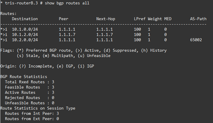
Now, this time, we can see that the the BGP route is shown as “feasible” and its installed it, this is because the route to that network is now known to Router C and Router G because its being learned via OSPF; and thus BGP can install that route!
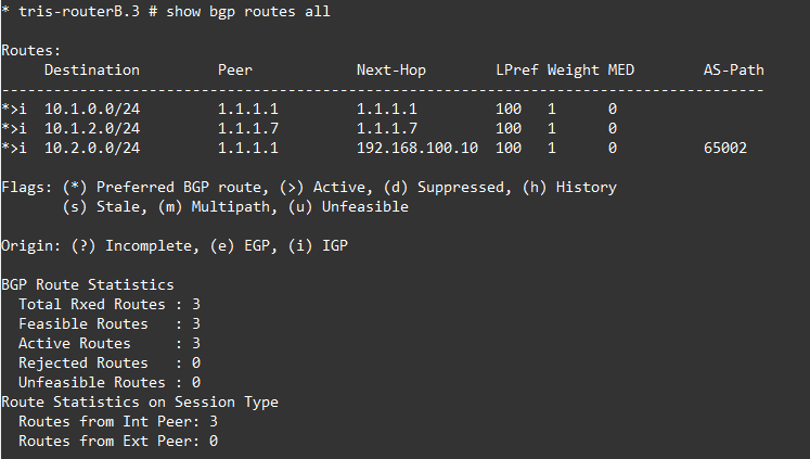
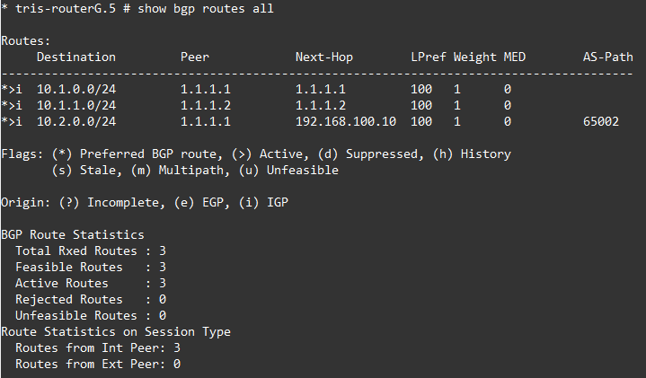
And the network is reachable as expected.
Step 5 – Loss of a Link
Right, now let’s repeat the test we did in the previous article and down the link between Router A and Router G.
In this case we’re doing this with the use of Option 2 – Add RouterA→RouterC point to point link subnet to OSPF in place to ensure that the route learned by Router B and Router G is reachable (feasible).
Router A → Router G Link Fails
If the link between Router A and Router G fails, we’d expect the BGP Neighbour (peering) between Router A and Router G will still up, and all the routes that Router G has learnt will continue to be: 1. in its routing table (i.e. feasible) and 2. reachable!
So, Router G’s RouterG-LAN1 (10.1.2.0/24) network should be able to reach the LANs that are routed on Router A, B and C, i.e. RouterA-LAN1, RouterB-LAN1 and also RouterC-LAN1, and vice versa.
Right, down the link between Router A and Router G.
Router A
disable port 4Then on Router A and G, we observe BGP Neighbours, as we can see, they are all still there, because we are using the Loopback addresses, all the BGP Neighbours can still reach each other, even though the underlying physical topology has changed with the loss of the link between Router A and Router G. Now, rather than this BGP Neighbour (peering) failing and causing a problem. The BGP Neighbour (peering) remains because the Router A and Router G Loopback IP Interfaces (used for the BGP Neighbour configuration) are still reachable, with OSPF providing a different route between these via Router B.
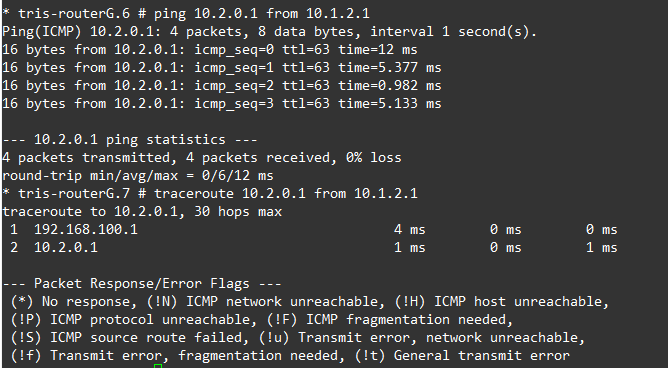
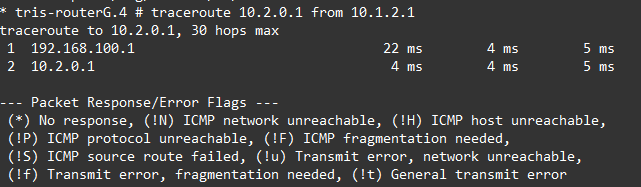
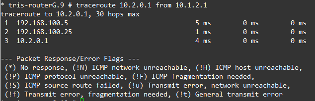
We can observe this by looking at a traceroute, below is the before and after (failure) of the traceroute from Router G to Router C’s LAN network, as we can see….it changes!
Bring the link back up again by re-enabling the port.
What happens if Router B to Router G’s link is downed isn’t shown, but the behaviour is the same, the traffic instead flows from Router G, to Router A, then onto Router C.
Conclusion
We have now got a working iBGP area which seems to be able to cope with anything we throw at it, we don’t have any oddities that only appear when a particular link fails. We’ll now continue to investigate how iBGP can work by adding more routers to our environment to increase the resilience i.e. extra links between AS Blue 65001 and AS Green 65002, which will increase the complexity, and so mean we’d need further develop our topology to cope.