We’ll continue to explore Internal BGP (iBGP) in this next part of our deployment. We are going to be deploying another route in the AS Blue 65001. Remember that eBGP is used between AS and iBGP is used within an AS.
Be aware however, that this lab topology is flawed in terms of its configuration, but it shows up how Internal BGP (iBGP) works and what design choices you need to make to ensure it works as you want.
So in this case our third router, Router G, will be linked to Router A via a single link and to Router B via a single link. Router A and Router B will still have a link between them, forming a triangle topology. There’ll also be another new LAN network setup for testing on Router G called RouterG-LAN1 with an IP address from the range 10.1.0.0/16, so 10.1.2.0/24 and will again have an interface on 10.1.2.1.
To comply with the rules of iBGP, we’ll have all three of the routers connected in a “full mesh” ergo, all the routes in the AS are connected to all the others. Router A will act as the bridgehead that exchanges routes to and from Router C within the other AS Green 65002.

The example assumes that you have the three Routers within the AS Blue already powered on, cabled up and ready for configuration; and the existing Router within AS Green.
Next Hop Self Recap
In our current network design, we are going to be using “Next-Hop-Self” within the AS Blue 65001. A method that ensures that routes that are learned by iBGP (where the source of the route is outside that AS) have their NEXT_HOP attribute rewritten so, when a Router advertises routes to a neighbour router, it rewrites the NEXT_HOP to itself. Simply put, this resolves the issue where a Router e.g. Router B, learns a route from Router A via iBGP, but because Router A has learnt this via eBGP it passes it on with a “next-hop” destination that Router B can’t reach, ergo Router B never adds this to its route table, because the route is unfeasible.
As mentioned in the previous article, the use of “next-hop-self” is not a fix all option, but in certain situations, such as this one where we have a single egress point, i.e. an edge/bridgehead, it is a useful simple approach.
Step 1 – Configure Point to Point Links
First steps are to configure the point to point links between Router A and Router G and Router B and Router G.
Router A
We add the point to point IP and VLAN for this link, ensuring it is enabled for routing.
create vlan "RA-RG"
configure vlan "RA-RG" ipaddress 192.168.100.1/30
enable ipforwarding vlan "RA-RG"
configure vlan "RA-RG" add port 4 untagged
Router B
We add the point to point IP and VLAN for this link, ensuring it is enabled for routing.
create vlan "RB-RG"
configure vlan "RB-RG" ipaddress 192.168.100.5/30
enable ipforwarding vlan "RB-RG"
configure vlan "RB-RG" add port 4 untagged
Router G
We add the point to point IP and VLAN for this link, ensuring it is enabled for routing.
create vlan "RG-RA"
configure vlan "RG-RA" ipaddress 192.168.100.2/30
enable ipforwarding vlan "RG-RA"
configure vlan "RG-RA" add port 1 untagged

create vlan "RG-RB"
configure vlan "RG-RB" ipaddress 192.168.100.6/30
enable ipforwarding vlan "RG-RB"
configure vlan "RG-RB" add port 2 untagged
You should now be able to ping from the interface IP on Router A to the interface IP on Router G and the interface IP on Router B to Router G for these newly added links, if you cannot verify your configuration before proceeding further.
Step 2 – Configure Loopback Interface for Router ID
We then need to add the loopback interfaces for the Router ID on Router G.
Router G
Making this a loopback interface means it comes up and stays up, even there are no ports assigned or live in that VLAN.
create vlan "RouterG-LP"
configure vlan RouterG-LP tag 1117
enable loopback-mode vlan RouterG-LP
configure vlan RouterG-LP ipaddress 1.1.1.7 255.255.255.255
enable ipforwarding vlan RouterG-LP
Step 3 – Configure VLAN and Interface for Example LAN (Subnet) on Router G
We’re going to create a VLAN and interface on Router G to be example LAN network, i.e. default gateway, so we can use these for testing and more importantly as networks we’re advertising via BGP.
We’re enabling loopback on this for now, because it doesn’t have any active ports in the VLAN to keep it up, but it needs to be up for us to use it for testing.
Router B
So we’ll create a VLAN called RouterG-LAN1 (tag 1007) on Router G with the interface IP address of 10.1.2.1/24 (i.e. network subnet 10.1.2.0/24), all within the summarised network of 10.1.0.0/16.
create vlan "RouterG-LAN1" tag 1007
configure vlan "RouterG-LAN1" ipaddress 10.1.2.1/24
enable ipforwarding "RouterG-LAN1"
enable loopback-mode vlan "RouterG-LAN1"
Step 4 – Enable BGP and Create Neighbour
Okay, now we are ready to enable BGP on Router G, but we’re also going to need to do some configuration on Router A and Router B too. Firstly, on Router G we’ll need to enable BGP and configure it’s AS number (same as Routers A and B because its in the same AS) and a Router ID too. Then, we’ll configure the BGP Neighbour to Router A and a BGP Neighbour to Router B (and vice versa back to Router G), the configuration for this is a bit different to what we did in the first part being this is iBGP rather than eBGP.
We are deliberately not setting “next-hop-self” on these neighbours so we can see the behaviour without, we’ll then add in “next-hop-self” in a later step to observe the differences.
Router G
We enable BGP, then we add the neighbour with Router A and B.
configure bgp AS-number 65001
configure bgp routerid 1.1.1.7
enable bgp

create bgp neighbor 192.168.100.1 remote-AS-number 65001
configure bgp neighbor 192.168.100.1 source-interface ipaddress 192.168.100.2
enable bgp neighbor 192.168.100.1

create bgp neighbor 192.168.100.5 remote-AS-number 65001
configure bgp neighbor 192.168.100.5 source-interface ipaddress 192.168.100.6
enable bgp neighbor 192.168.100.5
Router A
We don’t need to set up BGP, that was already done, we just need to add the BGP Neighbour to Router G.
create bgp neighbor 192.168.100.2 remote-AS-number 65001
configure bgp neighbor 192.168.100.2 source-interface ipaddress 192.168.100.1
enable bgp neighbor 192.168.100.2
Router B
We don’t need to set up BGP, that was already done, we just need to add the BGP Neighbour to Router G.
create bgp neighbor 192.168.100.6 remote-AS-number 65001
configure bgp neighbor 192.168.100.6 source-interface ipaddress 192.168.100.5
enable bgp neighbor 192.168.100.6
Verify
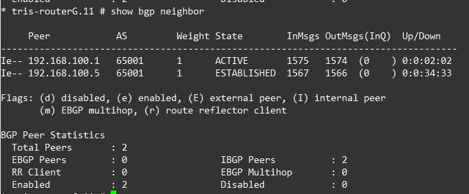
Before going any further ensure that you can see the BGP Neighbour adjacencies within the output of the “show bgp neighbor” command, the neighbours on Router B should be showing as state “ESTABLISHED” and that Router A and Router B router is showing as an “internal peer”, you can see this by the iBGP which can be seen by the “I” at the beginning for example:

Step 5 – Add Example LAN Subnet to BGP
In Step 3, we added an example LAN that we could use for testing, so we can actually advertise networks via BGP between the routers; and exchange some routes between them. Due to the limitations of the test lab at this stage, we don’t have any downstream switches connected to the routers, so we don’t have something real, so instead we’ll create the VLAN interface, but then make it a loopback, so the interface stays up artificially for testing purposes.
Once done, we’ll enable this for BGP, meaning that BGP will add these into the RIB.
Router G
We add the subnet that we want to have advertised.
configure bgp add network 10.1.2.0/24Step 6 – Verify iBGP Routes
Now the configuration is done, we can verify what is happening.
Verify
As expected when examining Router G, we can see the following in the BGP RIB. We can see the RouterA-LAN1 (10.1.0.0/24) subnet has been added to the route table and the RouterB-LAN1 (10.1.10/24) subnet has been added to the route table; these have been learnt via iBGP and because of the full mesh and that there is only a single “hop” to reach each the “next-hop” is directly accessible to Router G, therefore the route is “feasible”.
However, when examining the Router G route table, the route for RouterC-LAN1 (10.2.0.0/24) from the AS Green is not being added owing to it being learnt via iBGP, readvertised by Router A (from Router C) and the next-hop attribute being an IP address (192.168.100.10) that Router G has no route to.

Again this is an example of where the “next-hop” attribute can be used to resolve this problem, by re-writing the next-hop to Router A, which Router G will have a direct route to.
Add Next-Hop-Self to Router A → Router G BGP Neighbour
To resolve this we need to add the “next-hop-self”, which will involve adding this to the configuration on Router A in its BGP Neighbour to Router G, just like we did for Router B in the previous article.

Router A
We need to disable, configure and then re-enable the BGP Neighbour configuration.
disable bgp neighbor 192.168.100.2
configure bgp neighbor 192.168.100.2 next-hop-self
enable bgp neighbor 192.168.100.2
Verify Again
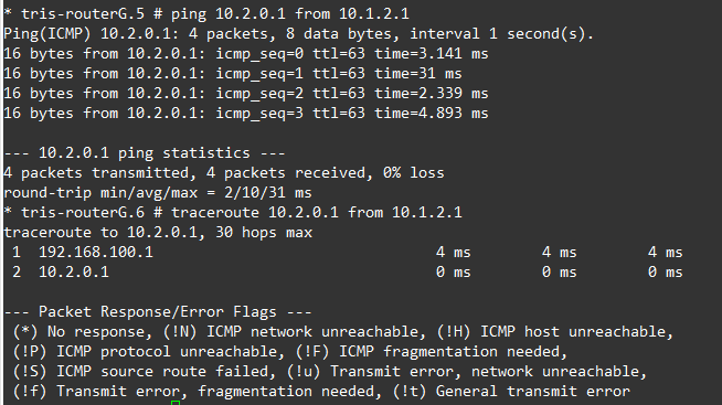
Now verify what has changed on Router G, as we can see the 10.2.0.0/24 route from Router C (the other AS) is now having its NEXT_HOP attribute changed to that of Router A, so its now considered “feasible” and added to the route table of Router G.

We are therefore now able to successfully ping from the RouterG-LAN1 VLAN interface to the RouterC-LAN1 interface.
Step 7 – Loss of a Link
In our AS Blue, we have this triangle of Routers, the multiple links providing some form of resilience.
We know that currently Router A, Router B and Router G can all ping each other’s LAN1 network interfaces, so that is a known good. So let’s verify what happens in a situation where a link fails.
Router A → Router G Link Fails
If the link between Router A and Router G fails, we’d expect that although the BGP Neighbour will go down, Router G’s RouterG-LAN1 network interface should still be able to reach RouterA-LAN1, RouterB-LAN1 and also RouterC-LAN1 so let’s verify that.
Router A
disable port 4We should now see that BGP Neighbour lose ESTABLISHED state on both Router A and Router G (it may take up to 180 seconds for it to notice), for example:
If on Router G, we now inspect the BGP Routes, we can see two problems. One the RouterA-LAN1 network subnet (10.1.0.0/24) is no longer showing in the route table, secondly, neither is the RouterC-LAN1 (10.2.0.0/24) so what is going on?

The answer is iBGP and the way it works.
iBGP has the rule that: “A route learned via iBGP must not be advertised to another iBGP peer”, also known as “iBGP Split Horizon”, So in this case Router G can no longer directly reach Router A, which means that in our current situation where the link between Router A and Router G has gone down, Router G is effectively cut off from reaching some networks (i.e. RouterA-LAN1 and RouterC-LAN1), as is Router A and Router C from reaching RouterG-LAN1. The reason is that although Router B is learning these routes from Router A and Router C, it can’t send these routes onto Router G without breaking the iBGP rule.
Sure we could turn on “next-hop-self” on the BGP Neighbour between Router G and Router B (which we have not yet done), but that wouldn’t help us! The rule of iBGP would still apply.
So now what?
Well, that is a very good question and one that shows this topology is architecturally wrong. And furthermore shows up a reason why using the “next-hop-self” approach is not a “fix all solution”.
We want to show this so you can understand how iBGP differs and although the triangle layout with Router A, Router B and Router G is valid for eBGP, with iBGP you can still use this, but we must change our configuration of iBGP to work within the way the protocol is intended to be used.
Essentially when the term “full mesh” is used this is actually a logical concept not a physical concept.
A router using iBGP must have a “full mesh” to every other iBGP router, however, it does not mean you need physical links to every other Router; it just means that every iBGP Router must have a BGP Neighbour (peer) with every other one (in the AS).
Of course if you have a very simple and small AS with say only two routers in it, much like we had the previous article, you have more options, but in our case with this three router topology, we essentially need to reconfigure.
So…..
What this means is that we now need to reconfigure the topology, so within AS Blue 65001, the BGP Neighbours are made based on a loopback IP address of each router, the loopback IP address of each router won’t change. Additional to this we’ll need to run another Routing Protocol within the AS which will distribute the loopback IP addresses of the Routers around, so that all the Routers A, B and G can all reach each other’s loopback IP addresses, to form the BGP Neighbour (peerings) and continue to do so, even if there are link failures that might stop a particular physical link between two particular Routers from working.
We first go backwards, to go forwards.
We’ll explore (and reconfigure our lab) with what we need to do to get this all working in the next article.