It’s key to understand BGP Timers to understand how and when certain actions will be taken by BGP.
BGP timers help the protocol answer these four fundamental questions:
- Is my neighbour alive?
- How long should I wait before declaring it dead?
- How often should I try to reconnect if it’s down?
- How fast can I safely send updates?
Everything else is a refinement of those.
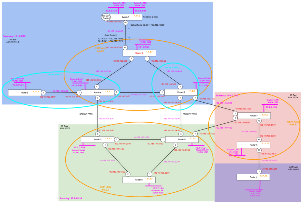
Topology and Configuration
We’re making some additional changes to the topology, we are adding two new routers, Router K and Router L, where Router K is added within AS Red (65003), but Router L is added into its own AS, called AS Purple (65004). These are slightly newer hardware so will give some options for later on in the series, but for now we’re just adding them so we have some additional routers tweak some settings on and see what happens!
Router F
We are enabling OSPF on Router F, then configuring it with the point to point link to Router K. And enabling BGP neighbour (peerings) to the Loopback addresses of Router K (Router L we’ll come to later), where Router K’s loopback route is carried via the IGP in this case OSPF.
create vlan "RF-RK"
configure vlan "RF-RK" ipaddress 192.168.100.61/30
enable ipforwarding vlan "RF-RK"
configure vlan "RF-RK" add port 49 untagged

configure ospf routerid 1.1.1.6
enable ospf

configure ospf add vlan RF-RK area 0.0.0.0 link-type point-to-point
configure ospf add vlan RouterF-LP area 0.0.0.0 passive

create bgp neighbor 1.1.1.12 remote-AS-number 65004
configure bgp neighbor 1.1.1.12 source-interface ipaddress 1.1.1.6
enable bgp neighbor 1.1.1.12
Remember that it being iBGP we must have full-mesh topology, but because we only have one other Router in this AS, i.e. Router K, we don’t need to do anything else other than create the peering. Router L will be in a different AS, therefore will use eBGP, so this rule (iBGP Split Horizon rule) does not apply.
Router K
Now we configure Router K, adding the point to point links, and the OSPF configuration.
create vlan "RouterK-LP"
configure vlan RouterK-LP tag 1212
enable loopback-mode vlan RouterK-LP
configure vlan RouterK-LP ipaddress 1.1.1.12 255.255.255.255
enable ipforwarding vlan RouterK-LP

create vlan "RK-RF"
configure vlan "RK-RF" ipaddress 192.168.100.62/30
enable ipforwarding vlan "RK-RF"
configure vlan "RK-RF" add port 49 untagged

create vlan "RK-RL"
configure vlan "RK-RL" ipaddress 192.168.100.65/30
enable ipforwarding vlan "RK-RL"
configure vlan "RK-RL" add port 53 untagged

create vlan "RouterK-LAN1" tag 1009
configure vlan "RouterK-LAN1" ipaddress 10.4.1.1/24
enable ipforwarding "RouterK-LAN1"
enable loopback-mode vlan "RouterK-LAN1"

configure ospf routerid 1.1.1.12
enable ospf

configure ospf add vlan RK-RF area 0.0.0.0 link-type point-to-point
configure ospf add vlan RK-RL area 0.0.0.0 passive
configure ospf add vlan RouterK-LP area 0.0.0.0 passive

configure bgp AS-number 65004
configure bgp routerid 1.1.1.12
enable bgp

create bgp neighbor 1.1.1.6 remote-AS-number 65004
configure bgp neighbor 1.1.1.6 source-interface ipaddress 1.1.1.12
enable bgp neighbor 1.1.1.6

create bgp neighbor 192.168.100.66 remote-AS-number 65005
configure bgp neighbor 192.168.100.66 source-interface ipaddress 192.168.100.65
enable bgp neighbor 192.168.100.66

configure bgp add network 10.4.1.0/24
Remember that we want the Router K to Router L point to point link to have OSPF enabled on the Router K side, so that subnet/network appears in OSPF, so the route will be seen as feasible to BGP, but crucially, it must be set to passive, because we don’t want it to be able to accept OSPF join requests from Router L (if that was ever accidentally configured).
Router L
Finally, we configure Router L, with the point to point links and the BGP configuration, we don’t need OSPF (or any other IGP) at the moment being there is only one router in the AS.
create vlan "RouterL-LP"
configure vlan RouterL-LP tag 1213
enable loopback-mode vlan RouterL-LP
configure vlan RouterL-LP ipaddress 1.1.1.13 255.255.255.255
enable ipforwarding vlan RouterL-LP

create vlan "RL-RK"
configure vlan "RL-RK" ipaddress 192.168.100.66/30
enable ipforwarding vlan "RL-RK"
configure vlan "RL-RK" add port 1 untagged

create vlan "RouterL-LAN1" tag 1010
configure vlan "RouterL-LAN1" ipaddress 10.4.2.1/24
enable ipforwarding "RouterL-LAN1"
enable loopback-mode vlan "RouterL-LAN1"

configure bgp AS-number 65005
configure bgp routerid 1.1.1.13
enable bgp

create bgp neighbor 192.168.100.65 remote-AS-number 65004
configure bgp neighbor 192.168.100.65 source-interface ipaddress 192.168.100.66
enable bgp neighbor 192.168.100.65

configure bgp add network 10.4.2.0/24
Verify
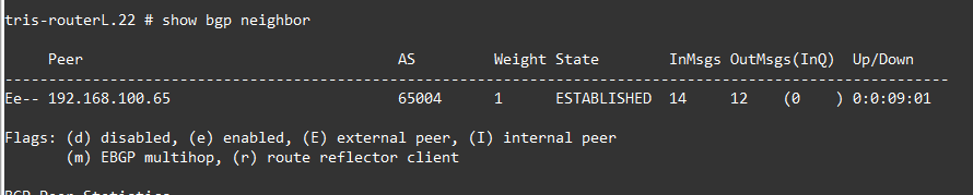
We now can check Router F, Router K and Router L, we should see our BGP Neighbour peering are working and that the Router K and Router L LAN Network routes are being distributed via BGP, so Router F is able to see a route for that too. Remember because Router F and Router K are within one AS (AS Red 65004) and Router L is on its own in its own AS; we don’t need to worry about issues with the iBGP Split Horizon rule, because all the routes these routers are learning are either direct via eBGP or are routes originating on that router and being transmitted on, ergo they are not hitting the limitation that you can readvertise a route learned from one iBGP to another (i.e. the Split Horizon rule).
Note at the time of writing Router F had no other active BGP neighbours because Router B and Router D were off due to an unknown power failure, hence why these are showing state “ACTIVE”.


We check the route tables too.

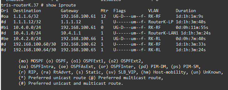
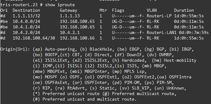
All the routes we are expecting are there, namely 10.4.0.0/24, 10.4.1.0/24 from within AS Red (65004) and 10.4.2.0/24 from AS Purple (65005).
Now we are ready to dig into the timers and how they work.
Tuning
It is worth noting that the BGP timers are tunable by System Administrators, there are benefits and drawbacks in tuning them however, so understanding when to change things and when not to is key.
Essentially tuning BGP timers for more aggressive detection of a dead peer for example is useful if you need faster detection (of failures); however things like BFD may be a better approach to use if you can. However, tuning means you really need stable, predictable and low latency links, ideally where you control both sides, or at least have a good rapport with those at the other end.
The downsides however is that when you’ve tuned timers (away from the defaults), any new peering will require manual configuration to get working potentially, additionally when tuning you are increasing sensitivity, at the expense of stability.
Timers
There are a number of BGP timers which we’ll explain and show some examples of. The timers help ensure stable and performant network operation by minimising the impact of flapping links and allowing a balanced configuration to improve BGP network convergence speed. Its worth noting that the moment you diverge from the default, you’ll need to ensure you have record of this; though these configurations can be made on a peer by peer basis, i.e. they are not global to the whole router.
Hold Timer (a.k.a Hold-Down Timer) and Keep alive Timer
The Hold Timer and Keep alive Timer will be explained together because: 1. it makes it easier to explain them, and 2. because they work together to determine when a link or peer failure has occurred.
Keep alive Timer
The Keep alive Timer is a mechanism that sends periodic “I’m alive” messages between BGP neighbours (peers) to let the other side know that 1. its neighbour is still there, 2. the link is still working (and capable of sending data). So, when a BGP peer is in ESTABLISHED state, it sends a keep alive every 60 seconds (by default) to the neighbour, and the neighbour is also sending its keepalives vice versa; so essentially as long as the BGP session is up, a keep alive is sent every 60 seconds (by default).
Each Keep alive message must arrive before the Hold Timer expires (otherwise a router will take action), we’ll discuss this in a moment.
Having a control plane mechanism like this allows for BGP to detect failures without having to rely on the data plane, but also allows BGP to detect a failure faster than waiting for the TCP session to timeout, which can be a number of minutes (depending on your operating systems and platform).
Hold Timer
The Hold Timer is a mechanism closely related to the Keep alive Timer. It is the maximum time a router will wait without hearing from its BGP neighbour peer before it decides that the peer is dead and removes any routes using that peer from its routing table.
The default is that the Hold Timer is 180 seconds (for Cisco, other manufacturers may vary), the normal rule of thumb is that the Keep alive Timer should be set to one third this time, i.e. 60 seconds in this case. Meaning a particular router (BGP peer) would need to fail to send, or the local router would need to fail to receive three consecutive Keep alive messages. The Keep alive Timer must be less than the Hold Timer obviously, otherwise the BGP peer session would be torn down before it even had a chance to receive a Keep alive message!
Keep alive Timer ≈ Hold Timer / 3
You need to remember though that every time a Keep alive message is received (or Update message is received whichever is sooner), it resets the Hold Timer back to 0 again; and the Hold Timer then starts counting up until it receives the next Keep alive (or Update) message. If of course it doesn’t get either within the Hold Timer time of 180 seconds, it marks the BGP neighbour (peer) as dead; and removes its routes as a viable path for traffic, but 180 seconds is 3 minutes….that’s a long time for traffic to not be flowing before “the network” takes action (we’ll discuss this in a moment).
The Hold Timer and Keep alive Timer are negotiated as the BGP Neighbour peering is established, if both are configured to the same values on each side (i.e. each peer) then there is nothing to do. If however one side is set to a shorter time, then that is what is used, hence they don’t need to match, they negotiate the shorter time. The Keep alive Timer is not normally negotiated and is set to a third of the hold time by default.
RFC4271 suggests that the Hold Timer should be 90 seconds as an initial value.
There is an important limitation however, that was mentioned earlier; and that is around it taking 180 seconds for a router to determine that a path is no longer usable, that’s potentially a long time to be potentially disrupting network traffic while the “the network” sorts out what is going on.
So you could reduce this time (Hold Timer) down to say 60 seconds, in which case the Keep alive Timer would be a third of that so 20 seconds. However, changing this needs to be done with consideration, firstly the shorter the timer durations, the higher the CPU load on the router (especially with many/multiple peers are being used), secondly the network can become more twitchy, if you have a link that starts to flap (a flapper) or is changing state frequently, having a Hold Timer that is shorter could mean its recognised faster, but in doing so you are generating more update messages and changes of route availability across your network, which could in turn cause its own issues with traffic flow.
So what can you do to detect broken BGP sessions/peers more quickly? Well one is using what we’ve discussed, tweaking the Hold Timer settings to make it more aggressive at identifying and taking action, we’ll explore this in a moment, the other is using a technique sometimes known as “fast external failover” (Cisco) which pegs the BGP session to if the interface used is up or down or not. If the interface used for a particular BGP neighbour (peer) goes down, the router immediately tears down that BGP session, without waiting for the Hold Timer, thus making the reaction much quicker; however this doesn’t cope with things where the link is lost in the middle and the interface stays up!
Example
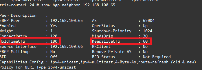
So on Router L, let’s see what we have configured, in the output below, you can see we have a Hold Timer of 180 seconds and a Keep Alive Timer of 60 seconds, as you can see a third of the Hold Timer.
Example – Link Loss (Interface Down)
So lets shutdown the link between Router K and Router L and observe what happens. Because of the Hold Timer, we are expecting that if we shut down the port on Router K, it will be up to 180 seconds before the BGP Neighbour peer is declared dead, and therefore returns to INIT state again, thus removing any routes learned from that peer.
So on Router K, we issue: disable port 53 to shut down the link between Router K and Router L.
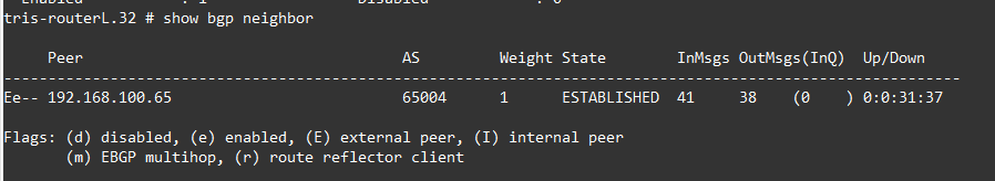
But when we examine Router L, it thinks it’s still established!
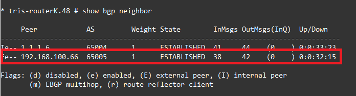
As does Router K.
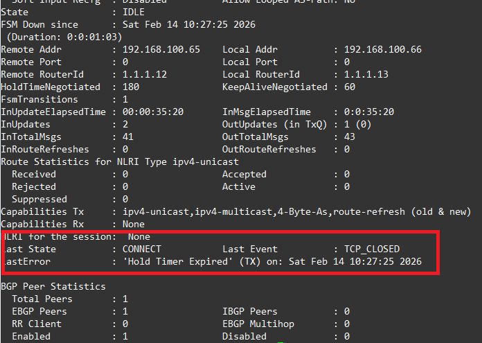
But after 180 seconds, we then see when running show bgp neighbour 192.168.100.66, the detail where we can see it’s finally detected the BGP neighbour has gone and then removes it from the Route Table, as we can see its showing the reason as “Hold Timer Expired”.
Fast External Failover
There is functionality called by Cisco “fast external failover”, the same functionality exists in Extreme Networks XOS. This functionality means that the BGP Neighbour state is pinned to the interface state, meaning in our example above, the BGP neighbour (peer) would have immediately swapped to INIT state when the interface went down, rather than having to wait for the Hold Timer to expire.
The downside of this however is that a flapping link could cause Route Table instability by continually raising and dropping routes in the routing table. The recommended approach therefore is to either tweak the Hold Timer (and Keep alive Timer) or better still use a mechanism such as BFD (discussed in a later article).
It really should be enabled on both sides of a link, it is a global setting, therefore affects all interfaces/ports, which may not be ideal in some circumstances. You can enable it globally by running:
enable bgp fast-external-falloverWhen performing the same test as shown above, the BGP Neighbour state moved immediately to INIT state, without waiting for the hold timer; obviously there are risks with this as mentioned above.
Example – Tweak the Hold Timer (and Keep alive Timer)
We’ll now tweak the Hold Timer on Router L, swapping the Hold Timer to 45 seconds (rather than 180 seconds), meaning the Keep alive Timer would need to be set to a third of this, so 15 seconds. We apply as follows:
Router L
We set the Timer configuration on the BGP Neighbour configuration individually, this isn’t a global setting, but you must first disable the neighbour, make the change and then re-enable it.
disable bgp neighbor 192.168.100.65
configure bgp neighbor 192.168.100.65 timer keep-alive 15 hold-time 45
enable bgp neighbor 192.168.100.65
Now we examine the output of: show bgp neighbor 192.168.100.65, and we can see indeed that the Hold Timer and Keep alive Timers have been changed to 45 and 15 seconds respectively. We see this on both Router L and on Router K, because it is negotiated to the lowest value, i.e. it uses whichever value is configured lowest.

Now when disabling the port (interface) on Router K, like we did earlier, rather than having to wait 180 seconds for the BGP Neighbour to change to the INIT state and the now unavailable routes be removed, this happens in only 45 seconds!
Example – Link Loss in the Middle
Another noted scenario covers what happens if your Router is not connected directly to another Router with a specific link, i.e. your Router is neighbouring to a BGP peer that is not directly connected meaning if there was an issue with the link, the only way you’d know is that traffic stopped flowing, you would not get any indication via a loss of a link; for example:
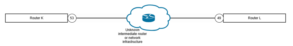
These kinds of situations exist, typically however when you are dealing with WAN or MAN links between sites across the country or the world. The telecom provider delivers you a link, which may be not be “dark fibre”, i.e. not a dedicated link where the photons you put in at one end are the same coming out of the other end of the link, it may have intermediate infrastructure/routers/switches in the middle that are invisible to you the end customer. Therefore, the implications of this are what was mentioned above.
How can you deal with this?
Well, the same sorts of techniques discussed earlier, you can either tweak the Timers to identify the link loss sooner, because the BGP Hold Timer will expire due to the Keep alive messages not being received as expected and in a timely manner, or by use of BFD (covered in a later article).
Connect Retry Timer
The Connect Retry Timer is exactly what it says, it’s the amount of time the router waits before retrying a BGP TCP connection when it is in INIT or ACTIVE state.
Typically, this is 120 seconds, but can vary by the manufacturer.
Extreme Networks XOS uses 120 seconds, but since version 31.6 it is now configurable, https://extreme-networks.my.site.com/ExtrArticleDetail?an=000108071#:~:text=Answer,and%20added%20to%20the%20configuration.
You might want to change this so that the Router more aggressively attempts to bring a connection up after it is lost, the risks of shortening this time is increased CPU usage, constant connection attempts and the risk of making a flapping link have more effective than it otherwise would have by removing a form of “dampening”.
Router Advertisement Timer (MinRouteAdvertisementInterval)
I couldn’t at the time of writing find much about this in Extreme Networks XOS, but the Router Advertisement Timer is present, by a typical default is 30 seconds for eBGP Routes and 0 seconds for iBGP routes. Extreme Networks appears to use eBGP 30 seconds and iBGP 5 seconds respectively: https://documentation.extremenetworks.com/exos_30.2.2/GUID-F0F7E08D-A308-44BC-A57D-0D12FA02EE32.shtml
So, what does it do? It specifies the minimum time between successive updates for the same network route prefix.
So, from Router L to Router K we are advertising the route 10.4.2.0/24, i.e. Router L’s LAN network. This route being advertised from Router L to Router K, and it being an eBGP route will be subject to a 30-second minimum route advertisement interval, to dampen this route being readvertised within 30 seconds due to a change.
It is acting at route (network prefix) level means its very granular and can dampen route changes across a very large network, like the Internet; to help prevent update storms due to flapping routes, or rapidly changing routes during maintenance.
You’ll notice at the iBGP level this defaulted to be 5 seconds, it assumed because iBGP is being used the network is more stable and managed within in a single entity/organisation, so assumes a more controlled environment (and potentially a smaller one), thus the need to suppress route changes is not as important.
Route Damping Timer
The BGP Route Dampening Timer is again a mechanism along the lines of the Router Advertisement Timer. As specified in RFC 4271 and RFC 2439, the BGP Router uses dampening approaches to minimise the impacts of route changes and the impacts of their propagation through the network due to flapping links. Each transition of state for a network route (from down to up, or up to down) requires a withdrawal or advertisement message to be sent, flurries of these can overload Routers and cause issues, not to mention potentially negating the benefits of having multiple routes to a network, if the failover to the backup link is not: 1. clean and 2. stable enough that traffic can start using it, before it failing back, and thus disrupting network traffic once more.
On Extreme Networks XOS, you can enable this dampening on a per BGP Neighbour basis.
If we wanted to add this on Router L for example, we’d use a command like the below:
configure bgp neighbor 192.168.100.65 dampening half-life 15 reuse-limit 750 suppress-limit 2000 max-suppress 60We’d likely want to add the same on the other side of the link also, to ensure the routes are dampened both ways, but this is a decision during network design to consider the impacts during different scenarios.
You can see information about this with:

Explanation
So what actually is it?
Well, it’s basically a method to apply a penalty to a link that has flapped, so that although the link has come back up, it dampens or holds the routes learned via that BGP Neighbour in order to reduce/eliminate the effects of the flapping; essentially gives it a penalty, like a time-out in basketball, where a player is removed from the field for a period of time, even though they are still in the game; and will return at some point.
It can be a bit complicated to explain but here’s a rough guide to how it works.
There are five attributes involved:
- Penalty: 1000
- Suppress-Limit: 2000
- Half-Life: 15 minutes
- Reuse limit: 750
- Maximum Suppress-Limit: 60 minutes
So lets run through, say Router L’s link starts to flap and thus the routes it is advertising will also flap:
- Each time a route flaps, a penalty on that route is increased by 1000. Let’s say it flaps 3 times, so goes to a penalty of 3000.
- When that route’s penalty goes over 2000, i.e. it allows 2 flaps before dampening, the route starts to be dampened.
- Once the dampening is in place the router doesn’t add this route into the Route Table of the router, and it won’t advertise it.
- So now dampening is in place, when it learns about this route (with a penalty) again, say because the flapping link has now come up again and the route is being advertised; the Half Life Timer is started, after 15 minutes (its configuration), the penalty is reduced by 50%. So in this case penalty value for this route is changed to 1500.
- But now this route won’t be added to the Route Table nor will it be re-advertised unless it is below the Reuse Limit, 750 in this case.
- After another 15 minutes (Half Life), the penalty is reduced by 50% again taking it to 750, not quite enough yet.
- After another 15 minutes (Half Life), the penalty is reduced by 50% again taking it to 375, which is below the Reuse Limit, so the route is now added to the Route Table and re-advertised once more.
- Once the penalty value is below 50% of the Reuse Limit, so another 15 minutes later again, it is removed completely, or it would forever go on halving which wouldn’t be very helpful!
There is a downside to this however, where in some situations routes may end up being black holed because of misconfiguration that means once a route flaps it can never end up being re-added to the Route Table!
Full information on this topic can be found in page 232 on: https://documentation.extremenetworks.com/exos_commands_22.1/downloads/EXOS_Command_Reference_22_1.pdf
Idle Hold / Delay Open Timers
These are a couple more timers that are worth a mention.
The first is Idle Hold Timer, this timer is used when a BGP Neighbour transitions from ESTABLISHED to INIT state, rather than just immediately starting to reconnect again, the Idle Hold Timer holds the IDLE state for a period of time to stop it constantly attempting to connect immediately after a flap (or link failure), it’s basically a bit of dampening. After the Hold Timer expires, the state is free to attempt connections again.
The Delay Open Timer (or Open Delay Timer) is a timer that is used to delay the first BGP open message being sent after the TCP three-way handshake is first established, again a form of dampening, to make the network(s) less “twitchy” to changes.