
Was working recently with some colleagues on their coursework, where they had a need to configure a Cisco ASA Firewall to prepare a network topology that met certain criteria. They were using Cisco Packet Tracer, but were having a problem creating sub-interfaces (for each VLAN), it seemed that Cisco Packet Tracer (or the current version of it) would throw an error when they attempted to configure it. We eventually proved the configuration would work by using a real Cisco ASA Firewall, but that then led to how could we test the firewall with the Internet.
The Cisco ASA Firewall does support PPPOE, which allows you to use it with any BT Openreach FTTP Internet service. In this very simple example configuration we are setting up the Cisco ASA Firewall to provide a simple one interface (outside) and one interface (inside) configuration that NATs the internal range to a single outside static IP address. The configuration is enough to illustrate how the PPPOE works, but wouldn’t include everything you’d want in a configuration, such as the administration/management configuration, logging etc.
Firstly the physical connections, your FTTP will typically be provided via an ONT (Optical Network Terminator), sometimes called an “Openreach Modem”.
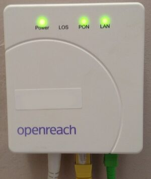
These are not supposed to be end-user (customer) configurable, and you don’t need to do anything to this, all you do is run an Ethernet cable from the ONT to the Cisco ASA Firewall, in my example this is interface 1/1, which will be the “outside” interface. You then run interface 1/2 the “inside” interface to your local LAN switch.
We’ll be NATing the whole of the internal range behind the single IP address on the “outside” interface.
General Configuration
You can substitute in your own IP address ranges, ISP name and ISP DNS servers as applicable. We are setting the MTU on the outside interface to 1492 (bytes) which is the normal MTU on the BT Openreach network. Your inside should remain at 1500 (bytes) however.
int gigabitethernet1/1
 nameif outside
 security-level 0
!

interface GigabitEthernet1/2
 nameif inside
 security-level 100
 ip address 192.168.1.1 255.255.255.0
!

mtu outside 1492
mtu inside 1500

object network obj_any
subnet 0.0.0.0 0.0.0.0
nat (inside,outside) dynamic interface
class-map inspection_default
match default-inspection-traffic
!
policy-map type inspect dns preset_dns_map
parameters
message-length maximum 512
policy-map global_policy
class inspection_default
inspect dns preset_dns_map
inspect ftp
inspect h323 h225
inspect h323 ras
inspect rsh
inspect rtsp
inspect esmtp
inspect sqlnet
inspect skinny
inspect sunrpc
inspect xdmcp
inspect sip
inspect netbios
inspect tftp
dhcpd address 192.168.1.100-192.168.1.200 inside
dhcpd enable inside
dhcpd dns <ISPDNS 1> <ISPDNS 2> inside
http server enable
http 192.168.1.0 255.255.255.0 inside
aaa authentication http console LOCAL
PPPOE Configuration
The PPPOE configuration is fairly straight forward, you create a VPDN group, substitute in your ISP login credentials, then apply it to the “outside” interface, 1/1 in this case.
vpdn group PLUSNET request dialout pppoe
vpdn group PLUSNET localname <USERNAME>
vpdn group PLUSNET ppp authentication chap
vpdn username <USERNAME> password <PASSWORD>
dhcpd auto_config outside

int gigabitethernet1/1
 ip address pppoe setroute
 pppoe client vpdn group PLUSNET
!
Once configured after a few minutes you should all being well find the PPPOE connection has dialed up and you have been assigned an external IPv4 IP adddress.
Troubleshooting
To show the current PPOE client configuration you can use:
# show ip address outside pppoeTo see the debug messages:
# [no] debug pppoe {event | error | packet}To see the current PPPOE session(s), you can use:
show vpdn session [l2tp | pppoe] [id sess_id | packets | state | window]Some other useful commands are:
show vpdn
show vpdn session
show vpdn tunnel