
An Arista Network uses two main approaches for the routing and switching of traffic across the network; there are others, but these are the main ones to consider.
- Raw Routing – The first approach is what we’re calling “Raw Routing” traffic will be routed directly across the Arista network without VXLAN encapsulation. It is typically routed at the Leaf (as close to the hosts as possible), routed resiliently with Virtual Router, which is where MLAG is also used to provide uplink resilience from the hosts across two Leaf Switches. In this case a VLAN (network) resides only within a Leaf Switch pair, and is not stretched elsewhere across the network. Uses are things like which have high performance demands and which are connected to specific Leaf Switches and routed close to the host itself there.
- VXLAN Backed Networks – The second approach is what we’re calling “VXLAN Backed Networks”, these are networks which aren’t just routed directly across the network in a traditional way and instead use vTEPs on Leaf Switches to allow them to be stretched across the underlying routed network and so a Layer 2 can be presented elsewhere on the Arista Network for the connection of Hosts. Uses are where you need devices to be connected across Leaf Switches, or in different areas altogether; the key thing is that the VLAN (network) spreads outside of its originating Leaf Switch areas.
Raw Routing (using BGP) with Virtual Router and MLAG Leaf Example Pattern
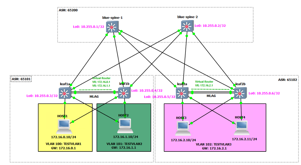
The example given here is a simple example pattern of what a Raw Routing – Raw Routed (using BGP) Network would look like, the key features of this are:
- Leaf Switches are uplinked to the Spine with point-to-point routed links running BGP protocol to carry routing information of any “User/Host Facing Networks (VLANs)”.
- Layer 3 – The Leaf Switches use Virtual Router (akin to VRRP) to provide resilient Leaf (edge) routing for networks (VLANs) that are hosted on the Leaf Switch pair.
- Layer 2 – The Leaf Switches uses MLAG to provide resilient layer 2 VLAN network access to connected hosts, with in-build loop prevention.
- The Leaf Switches have an interlink between them that is a LAG (Port-Channel) to provide resilient connectivity between Leaf Switch A and Leaf Switch B, required to avoid the MLAG going “split brain” if the ISL (interswitch link) was to fail.
Be aware that a particular VLAN (network) is only present on this Leaf Switch pair, and is therefore routed at this particular Leaf Switch pair. If however there was a need for this network (VLAN) to also be available on another Leaf Switch pair, this would then be an example of where that network (VLAN) would use the VXLAN Backed Network scenario.
Git Repository: https://github.com/tristanhself/arista-networks-useful-patterns/tree/main/raw-routing
Example Topology
In our example topology, we have three networks (VLANs), each are routed on their local Leaf Switch pairs in what is known as an SVI (Switch Virtual Interface). So TESTVLAN1 and TESTVLAN2 are routed on leaf1a and leaf1b, and TESTVLAN3 is routed on leaf2a and leaf2b, of course in this case a host on leaf2a/2b cannot be placed into a VLAN that is only present on leaf1a/1b and vice versa. Each host is connected to its local Leaf Switch pairs via MLAG (so a bonded NIC host side). It uses the default gateway of its local VLAN, which is a Virtual Router (SVI), running resiliently between Leaf Switch A and Leaf Switch B. So a loss of a single Leaf Switch allows for Layer 3 (routing) and Layer 2 (switching) resilience via Virtual Router and MLAG respectively.
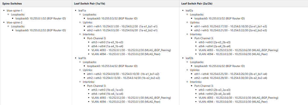
In terms of BGP, each Leaf Pair is in its own Autonomous System, as is each (pair or group) of Spine Switches. They all use BGP AS Dotted notation for clarity to represent that a particular Leaf Pair is “within” a particular Spine area (for the most part), although the key thing is AS number is different between the Leaf and Spine layers (and any other Leaf pairs for that matter).
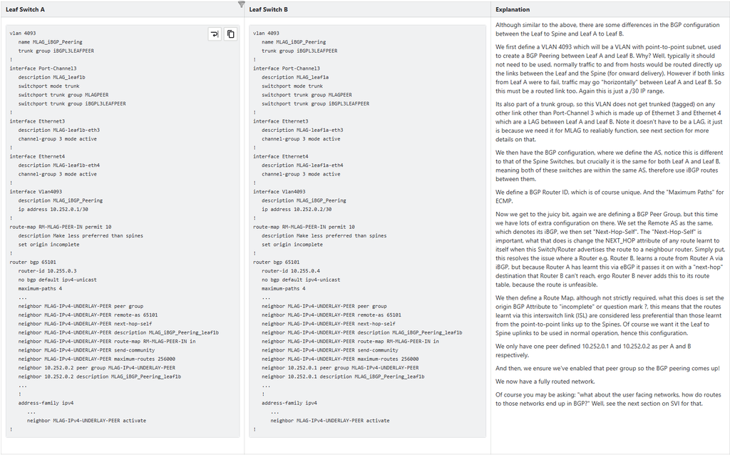
Each Leaf Switch pair has two special ISL (interswitch link) VLANs running between them (on-top of the user facing VLANs), these VLANs serve two purposes; one each. VLAN 4094 is a point-to-point VLAN used by the MLAG (Layer 2) for the communication between the two sides of the MLAG to ensure it works, it is therefore essential that this VLAN is resilience, hence the two physical links between Leaf Switch A and Leaf Switch B, and 2 is does not go anywhere else, hence the trunk group. The VLAN 4093 is a point-to-point VLAN used by the routing (Layer 3) SVI to allow traffic to be routed from Leaf Switch A to Leaf Switch B, if all uplinks on Leaf Switch A were to have failed; although not essential it is resilient, it gets it because of the need for the MLAG, and it does not need to go anywhere else, hence the trunk group. Its also noted that because each Leaf Switch is within the same BGP AS, this is an iBGP peering, not eBGP is the case between the Leaf Switches and their upstream Spine Switches.
AS, VLAN and IP Address Schema

Configuration Break-Down
We’ll now dive into the key parts of the configuration to examine how they work as part of the whole pattern.
Routing (Layer 3) – Border Gateway Protocol (BGP)
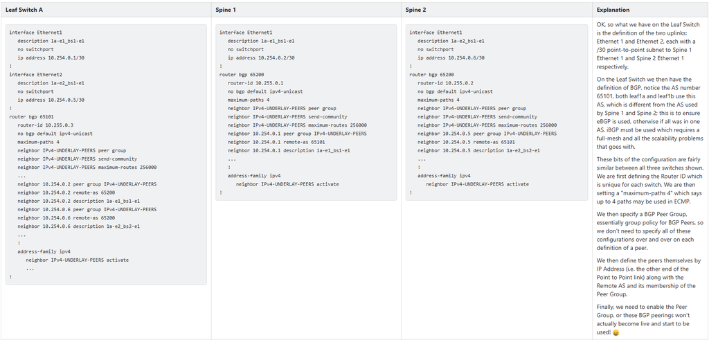
The routing between the Leaf Switches and the Spine and the Leaf Switch Pair (via the ISL) are key parts of the overal configuration. Due to the scale we’ll just look into a Leaf and a Spines and examine those, the rest of the configuration is just this repeated, so if you understand one, you can understand the whole.
Note that some bits of the configuration have been left out (or cut down) for clarity and brevity, notice the ellipses “…”, so refer to the git repository patterns for the full configuration.
Point to Point Links – Leaf to Spine
Point to Point Links – Inter-Switch Link (ISL)
Switching (Layer 2) – MLAG
For the MLAG configuration see the document: Arista Networks – Simple MLAG Configuration Example Pattern for full details.
Interface Trunk Behaviour
https://www.arista.com/en/um-eos/eos-virtual-lans-vlans
When an interface is marked as a trunk port with “switchport mode trunk” command such as the below:
interface port-channel 3
   switchport mode trunk
!
Then it means that all VLANs on the switch are trunked (tagged) across all trunk port, unless one or both of the following is true:
1. VLAN is Pruned from Port (i.e. not allowed on port)
What the below means is that the default behaviour to trunk (tag) all VLANs across the interface is changed, for this particular interface only the specified VLAN (100 in this case) will be trunked (tagged) across this interface, all others (4093 and 4094) will not be.
vlan 100
   name TESTVLAN1
!
vlan 4093
   name MLAG_iBGP_Peering
   trunk group iBGPL3LEAFPEER
!
vlan 4094
   name MLAG_Peer
   trunk group MLAGPEER
!
interface port-channel 3
   switchport mode trunk
   switchport trunk allowed vlan 100
!
interface Ethernet1/1
   switchport mode trunk
!
Although similar to the second method, it is different, this method says explicitly which VLANs are to be trunked (tagged) on an interface (where all the rest are “pruned” in Cisco parlance), while the second method (below using Trunk Groups) specifies to only trunk (tag) a particular VLAN on the interfaces which have the matching “label” (Trunk Group). If I was to add a new VLAN 200 to the switch, that would not automatically be trunked (tagged) on the Port-Channel 3 interface because it has an “allowed VLAN” list (hence it would be “pruned”, but it would be trunked (tagged) onto interface Ethernet 1/1 because that has no configuration to specify otherwise.
2. VLAN is Member of Trunk Group not Present on Port
What the below means is that when a VLAN has a trunk group configured, its no longer trunked (by default) and it will only be trunked onto interfaces that also have that trunk group, in effect pruning from all other trunk ports where the trunk group “label” doesn’t appear. You don’t need to go and manually add the pruning configuration for all the other trunk ports on your switch to not trunk the VLAN. Nice, saves lots of time!
vlan 100
   name TESTVLAN1
!
vlan 4093
   name MLAG_iBGP_Peering
   trunk group iBGPL3LEAFPEER
!
vlan 4094
   name MLAG_Peer
   trunk group MLAGPEER
!
interface port-channel 3
   switchport mode trunk
   switchport trunk group MLAGPEER
   switchport trunk group iBGPL3LEAFPEER
!
In this case VLAN 4093 will only be trunked on Port-Channel 3, because it is a member of the trunk group iBGPL3LEAFPEER and that trunk group only appears on Port-Channel 3 (rest of the configuration is not shown in this case), and VLAN 4094 is in the same position, being a member of the trunk group MLAGPEER which only appears on Port-Channel 3 it is only trunked (tagged) on this interface.
However, VLAN 100 is not a member of any trunk group, and so is automatically trunked (tagged) on any interface that is set to be a trunk port (assuming its not being “pruned” from a particular interface – which in this example it is not, see number 1).
Also note it is perfectly acceptable to have one or more Trunk Groups specified on an interface because it can mean that particular VLANs are trunked (tagged) on a number of interfaces, but conversely not on others; where the trunk group “label” does not exist.
It is not recommended to use these interchangably for a particular VLAN, or things can get very confusing!