
Within this article we are going to explore BGP Filtering, which is a method used to selectivity identify routes that are advertised (transmitted) or received from neighbour routers (and Autonomous Systems) in order to manipulate traffic flows, reduce memory utilisation or to improve security. It is a very common practice to use route filtering (also known as Policy), in fact we’ve touched on some of this in previous articles, where we have used Policies to manipulate the routes being advertised between the Autonomous Systems.
However, we are now are going to explore how we, as a System Administrator would use BGP Filtering to ensure we’re not sending particular routes to particular routers (and AS) in order to manipulate the way that traffic flows into and out of our network.
Topology
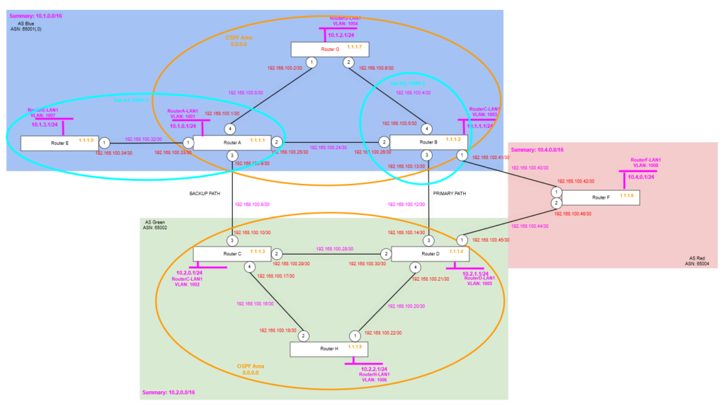
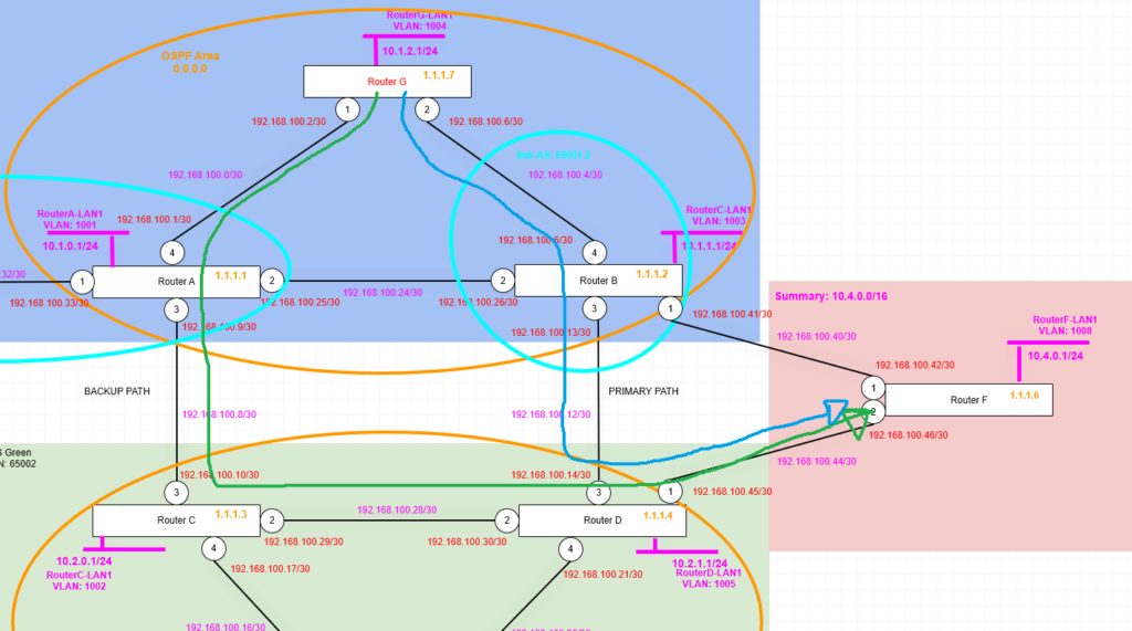
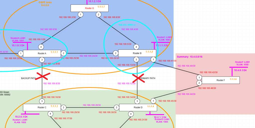
We’re going to be setting up our test environment as follows, we’re going to be adding a new AS called AS Red (65004), which will have its own LAN network, and we’ll want to be able to route traffic from AS Blue and AS Green into the network in AS Red, but in this case we’re assuming that the link directly between AS Blue and AS Red is not yet ready for production traffic (for some reason), therefore when AS Blue wishes to reach a network within AS Red, it must do so via AS Green.
We’ve left the BGP Confederation in place as it was at the end of the previous article, so AS Blue’s configuration is as shown in the topology.
Preparation
We need to get Router F all prepared so it will work, this also means we need to add some configuration to Router B and Router D too.
Router F
We’ll configure Router F first, will all the configuration to make it work as a BGP router. We’ll also create a LAN network which can be used for us to run some tests. We don’t need to enable OSPF in this case, because there are no other routers within AS Red, so nothing for it to peer to via iBGP.
create vlan "RF-RB"
configure vlan "RF-RB" ipaddress 192.168.100.42/30
enable ipforwarding vlan "RF-RB"
configure vlan "RF-RB" add port 1 untagged

create vlan "RF-RD"
configure vlan "RF-RD" ipaddress 192.168.100.46/30
enable ipforwarding vlan "RF-RD"
configure vlan "RF-RD" add port 2 untagged

create vlan "RouterF-LAN1" tag 1008
configure vlan "RouterF-LAN1" ipaddress 10.4.0.1/24
enable ipforwarding "RouterF-LAN1"
enable loopback-mode vlan "RouterF-LAN1"

create vlan "RouterF-LP"
configure vlan RouterF-LP tag 1116
enable loopback-mode vlan RouterF-LP
configure vlan RouterF-LP ipaddress 1.1.1.6 255.255.255.255
enable ipforwarding vlan RouterF-LP

configure bgp AS-number 65004
configure bgp routerid 1.1.1.6
configure bgp as-display-format asdot
enable bgp

create bgp neighbor 192.168.100.41 remote-AS-number 65001.0
configure bgp neighbor 192.168.100.41 source-interface ipaddress 192.168.100.42
enable bgp neighbor 192.168.100.41

create bgp neighbor 192.168.100.45 remote-AS-number 65002
configure bgp neighbor 192.168.100.45 source-interface ipaddress 192.168.100.46
enable bgp neighbor 192.168.100.45

configure bgp add network 10.4.0.0/24
Router B
Then add the point to point link configuration and BGP Neighbour peering on Router B. Also remember that for the route to be feasible within AS Blue, we need for the point to point link to be advertised into OSPF, so in this case we’re adding the point to point network “RB-RF” (VLAN) into OSPF. It’s added as a “passive” link because we don’t want it listening for OSPF adjacency requests.
create vlan "RB-RF"
configure vlan "RB-RF" ipaddress 192.168.100.41/30
enable ipforwarding vlan "RB-RF"
configure vlan "RB-RF" add port 1 untagged

create bgp neighbor 192.168.100.42 remote-AS-number 65004
configure bgp neighbor 192.168.100.42 source-interface ipaddress 192.168.100.41
enable bgp neighbor 192.168.100.42

configure ospf add vlan RB-RF area 0.0.0.0 passive
Router D
Then add the point to point link configuration and BGP Neighbour peering on Router D. Also remember that for the route to be feasible within AS Green, we need for the point to point link to be advertised into OSPF, so in this case we’re adding the point to point network “RD-RF” (VLAN) into OSPF. It’s added as a “passive” link because we don’t want it listening for OSPF adjacency requests.
create vlan "RD-RF"
configure vlan "RD-RF" ipaddress 192.168.100.45/30
enable ipforwarding vlan "RD-RF"
configure vlan "RD-RF" add port 1 untagged

create bgp neighbor 192.168.100.46 remote-AS-number 65004
configure bgp neighbor 192.168.100.46 source-interface ipaddress 192.168.100.45
enable bgp neighbor 192.168.100.46

configure ospf add vlan RD-RF area 0.0.0.0 passive
Verify
Before going any further let’s make sure that Router G, Router B and Router D all have working established BGP Neighbour peering, and that the LAN Network is appearing within AS Green and AS Blue, and their networks vice versa (from AS Red’s point of view).


Great, those all look to be in order. All are showing as “ESTABLISHED”, which means the BGP routers have made full peering with each other and are operational. Now let’s examine the BGP Route table on Router F, as we can see, we can see all the routes from the other two AS, where it’s picking a particular best path and showing various AS-Paths, i.e. different routes through the network it could take.

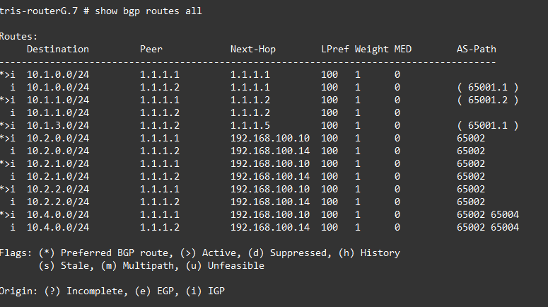
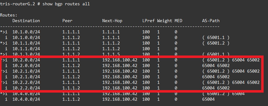
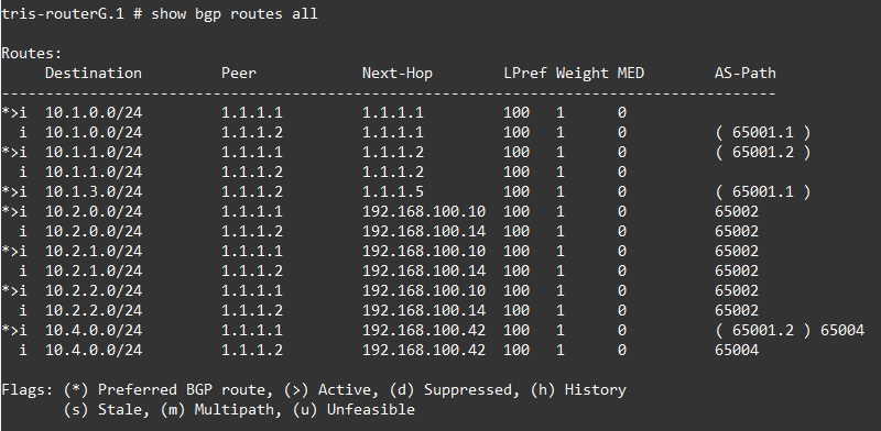
If we look at Router G, which is at the top of AS Blue, so a number of hops away, we can see it has a route for the 10.4.0.0/24 network, one via 65001.2, 65004, and then the other via 65004.
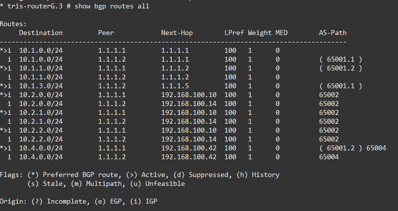
This is an interesting point here, remember at the end of the last article, we removed Router G from the sub-AS, so it was sitting alone within the AS outside a BGP Confederation, it means it is currently only seeing the route via 65001.2 then 65004, but also directly via 65004, which is odd, because it’s not directly connected, we may find this gives us a problem later on, but it may not, so we’ll carry on for now, but bear this in mind.
Example 1 – Not Advertising a Network via a Link using Policy
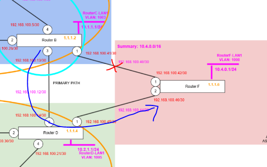
OK, so based on what we’ve seen above in the Route Tables, let’s say we want to ensure that Router B and Router F never communicate directly with each other, perhaps we don’t yet have permission for these two networks to talk directly with each other, so we can’t use this network for a direct peering yet. Here’s where we can use a policy to ensure that the network is not advertised from Router F to Router B, but ensure it is advertised from Router F to Router D, so that AS Blue can still reach the network(s) in AS Red (65004), but just not directly; it must go via AS Green instead.
Router F
We create a Route Policy on Router F, then apply it to that BGP Neighbour.
vi RF-RB-Out.polThe contents of the policy file would be as follows, notice how we are matching any 10.4.0.0/16 address and denying it. RF-RB-Out.pol
entry RF-RB-Out {
if match any {
        nlri 10.4.0.0/16 ;
}
then {
        deny ;
}
}
Now apply this policy to the BGP Neighbour (peering) from Router F to Router B.
configure bgp 192.168.100.41 route-policy out RF-RB-OutVerify
Then we verify, so what we are going to do is check the “transmitted routes” from Router F to Router B and Router D and see what we can see!
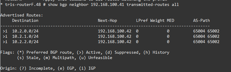

What do we notice about output for the Router F ↔ Router D BGP Neighbour peering (right – circled red), yes, that’s right, it’s transmitting the route for the 10.4.0.0/24 network (i.e. the local LAN connected to Router F). But, as you can see on the left output for the Router F ↔ Router B BGP Neighbour peering, we have no 10.4.0.0/24 being transmitted, so that means the Policy is doing its job, it’s not showing the Router F ↔ Router B link as a viable route to get from AS Blue to AS Red.
As an aside you’ll notice that Router F is passing on routes for 10.2.0.0/16 (the three /24 routes), this is means that Router B (and AS Blue) will see the path via Router F (AS Red) as another possible way to get from networks in AS Blue to networks in AS Green. We’ll explore this a bit more in Example 2 in a moment.
But before that, let’s quickly look at Router G, and see what that now shows, on the left is what the Route Table looked like before applying the policy and then on the right, after.

That’s right, notice the network 10.4.0.0/24 routes, one is installed, one is not. Its showing that it can get to AS Red (i.e. to the 10.4.0.0/24) network via Router A, then Router C and Router D (Green Line) which is the preferred route. It’s also showing another path (Blue Line), which is only two hops via Router B and then Router D, it’s a bit odd its chosen the former as the “best path”, because it has three hops. But remember this is BGP, a path that is more hops may be considered the better path than one using fewer hops. Exactly why its chosen this, would require us to understand the BGP path selection process to understand exactly why this path was chosen.
There is something else to consider here however!
What about the return traffic, for the traffic originating in AS Blue going to AS Red?
This is where we’d need the System Administrator of AS Blue on Router B to add a Policy that stopped AS Blue advertising 10.1.0.0/16 to AS Red directly via that link too, so it doesn’t appear at all as a possible route for traffic.
Otherwise, it will be found that 1. traffic will operate asymmetrically, i.e. the outward leg would go the right way, but the inbound leg would not! 2. Traffic originating from AS Red going to AS Blue would use this link, even when we don’t want it to!
Example 2 – Another Path (Route) Between AS Blue and AS Green via AS Red
An example where we are allowing AS Red to re-advertise networks from AS Blue and AS Green (and vice versa), so that AS Blue and AS Green could still communicate even if both the previous links have failed.
Router F
We’re going to temporarily remove the policy from Router F to Router B’s neighbour peering, so that traffic can now use that link between the two AS.
configure bgp neighbor 192.168.100.41 route-policy out noneAfter this, when inspecting Router B, we can see that the “best path” has changed to be direct from Router B to Router F.
Discussion
So what we’ve got going on here, is that AS Red and Router F, don’t apply any restrictions to the routes they learn and also pass on. So if Router F learns the route for 10.2.0.0/16 from AS Green (via Router D), it has that in its Route Table (RIB) and being that it has a route for that network it will pass it onto AS Blue via Router B; being that there are no policies in place to stop it from doing so.
What routes you do and don’t want to be exchanged and therefore which paths/links you do and don’t want used depends on what you’re trying to achieve.
Generally however, as a System Administrator you’d want to control the routes that you are transmitting to others as well as the routes you are receiving from others.
There are very good reasons for doing both of these however, for example, if your AS learns routes to a network, or networks, do you want to pass these onto others, because in doing so you could have traffic you were not expecting flowing across your network on the way to somewhere else. Additionally, if you just blindly accept all routes from another AS, you open yourself up to being exposed to errors or misconfigurations.
If the System Administrator of AS Blue added a typo to say they were advertising AS Green’s network range, and you just accepted that route from the BGP Neighbour, you could find yourself with routing issues, because traffic is not going in the intended direction. Sure you wouldn’t have stopped the administrator making the mistake in AS Blue, but, you’ve insulated yourself from it because you were only expecting the route 10.1.0.0/16 from AS Blue, not 10.2.0.0/16.
Scenario 1 – Allow AS Green Networks via AS Red
For this, we just do nothing, we’ve not got any policies applied, so that means that all the networks that Router F (AS Red) has learned will be passed onto its neighbours, for example we can see the routes being transmitted for Router F ↔ Router B (left) and Router F ↔ Router D (right).

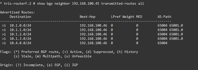
What this means is that if required AS Red will be used for connectivity between AS Blue and AS Green.
So let’s try that out and prove it. We as the System Administrator of AS Red might not want this to happen, we might not have sufficient capacity in our network to cope with all the traffic going between AS Blue and AS Green, so in the event of failure, we don’t want that traffic to come via AS Red, we’ll explore this 9and how we can stop it happening in a moment in scenario 2.
But for now we’re going to drop both links between AS Blue and AS Green, i.e. Router A ↔ Router C and Router B ↔ Router D, which will mean the only other way for the traffic to go would be via Router B ↔ Router F ↔ Router D, i.e. via AS Red.
Before Dropping Links
Before we drop the links, we’ll look at the route table of Router G and Router B. Specially we are interested in the routes to the network 10.2.0.0/16 and where they are going.
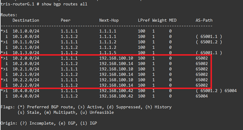

As we can see here, Router G sees either Router A or Router B as possible paths to 10.2.0.0/24 which is what is expected.
Router B sees three possible paths it could take to 10.2.0.0/24, one via Router B ↔ Router D (chosen as best path), one via Router B ↔ Router A, and finally one via Router B ↔ Router F, which is via AS Red.
After Dropping Links
We’ll now drop both the links between AS Blue and AS Green, i.e. Router A ↔ Router C and Router B ↔ Router D, which means the only surviving route would be via AS Red (Router F).

We can see that Router G (10.1.2.1) can still ping (reach) the network on Router H (10.2.2.1) via Router F and AS Red as shown in the traceroute.


So that confirms that AS Blue can still reach AS Green via AS Red.
But what if as the System Administrator of AS Red, you don’t want this to happen if there ever was the situation where both of their redundant links failed, maybe you’re links wouldn’t cope with all the traffic, your router wouldn’t cope with all the traffic, or you’ve not had an agreement to do so yet. See scenario 2 for how we can use policy in this situation to help.
P.s. we re-enable both of the links before we move to scenario 2.
Scenario 2 – Block AS Green Networks via AS Red
To ensure that AS Red is never seen as a possible route between AS Green and AS Blue (if both their links were to fail), we need to ensure that AS Red doesn’t pass on the route(s) it has learned from AS Blue and AS Green. We do that by applying policies to filter the routes, however, we need to ensure we’re not stopping AS Red from reaching the networks within AS Green and AS Blue!
Router F
You need policies on both BGP Neighbours, but blocking each other’s networks from being advertised. So we’ll create two policies as follows, firstly the one between Router B and Router F (AS Blue ↔ AS Red).
vi RF-RB-Out.polThen we set the policy to not send the route(s) learned from AS Green (10.2.0.0/16) to Router B (i.e. to AS Blue). We also specify the routes we do want to send in this case AS Red’s network 10.4.0.0/16.
entry RF-RB-Out1 {
if match any {
        nlri 10.2.0.0/16 ;
}
then {
        deny ;
}
}
entry RF-RB-Out2 {
if match any {
        nlri 10.4.0.0/16 ;
}
then {
        permit ;
}
}
Secondly the policy between Router D and Router F (AS Green ↔ AS Red).
vi RF-RD-Out.polThen we set the policy to not send the route(s) learned from AS Blue (10.1.0.0/16) to Router D (i.e. to AS Green). We also specify the routes we do want to send in this case AS Red’s network 10.4.0.0/16.
entry RF-RD-Out1 {
if match any {
        nlri 10.1.0.0/16 ;
}
then {
        deny ;
}
}
entry RF-RD-Out2 {
if match any {
        nlri 10.4.0.0/16 ;
}
then {
        permit ;
}
}
We now apply these policies to Router F’s two BGP Neighbour peering with:
configure bgp neighbor 192.168.100.41 route-policy out RF-RB-Out
configure bgp neighbor 192.168.100.45 route-policy out RF-RD-Out
Before
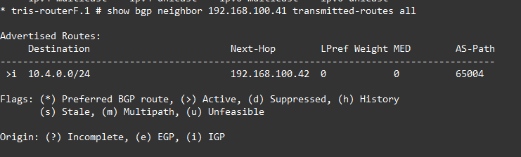
If we examine the routes that Router F is transmitting to Router B (left) and Router D (right) below, we can see the following:


So from Router D’s and Router F’s point of view. They see a path via AS Red (Router F in this case) as a possible route.
After
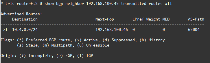
Once the policies have been applied to Router F, we now see that Router F is no longer re-advertising 10.1.0.0/16 and 10.2.0.0/16 which it has learned from the other ASs.
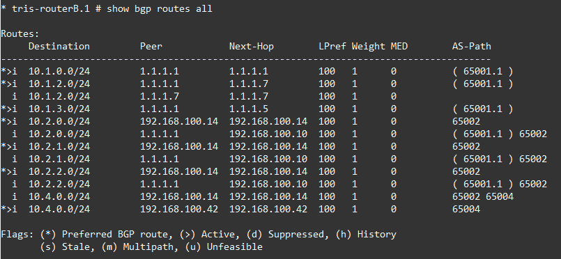
So, if we then examine the route tables on Router B and Router D, we see that there is no route for 10.2.0.0/16 or 10.1.0.0/16 (respectively) via AS Red (Router F).

OK, so now let’s prove this really is the case. We now drop both the links between AS Blue and Green, like we did earlier:
Then attempt to ping from Router G’s LAN interface to Router H LAN interface and what do we get?
Before
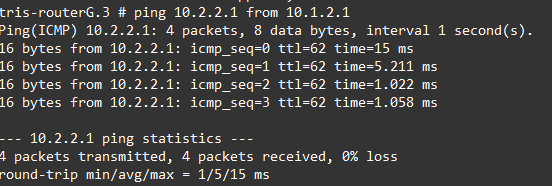

After

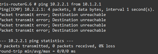

As we want/expect, AS Blue and AS Green no longer have a route between each other!
And Router G’s LAN interface can’t reach Router H’s LAN interface (or vice versa).
Before we finish, re-enable the two links, we disabled.
Conclusion
We’ve explored how you can use Policy (or filtering) to modify how routes are dealt with by routers, either accepting or denying them; but there is more you can also do.
In our case we’ve explored how we can stop a Router, Routers or an entire AS seeing a particular route as a “path” to another network (AS) by use of Policy. There are many reasons why you may do this, such as security, network traffic flow manipulation, bandwidth/performance limitations or concerns or just plain old, we don’t (yet) have an agreement for that AS to use our links/network in that way.