
Multicast is a networking method used to efficiently transmit data to multiple recipients simultaneously. Unlike unicast (one-to-one) and broadcast (one-to-all) communication, multicast is a one-to-many or many-to-many method where data is sent only to devices that are interested in receiving it, rather than to all devices on a network.
In multicast, devices that want to receive specific data streams (e.g. a TV channel) join a multicast group. Each multicast group is identified by a unique IP address from a reserved range (224.0.0.0 to 239.255.255.255 for IPv4). Devices that don’t belong to the group don’t get the multicast data, which conserves bandwidth.
If the sender and receiver of the multicast stream are within the same VLAN/Layer 2 segment then the multicast streams/groups only stay inside this one segment and additional mechanisms that allow streams to be “routed” such as PIM (Protocol Independent Multicast) are not required. If however a multicast stream sender is located in one VLAN (Layer 2 segment) and one or more receivers are located in one or more different VLANs (Layer 2 segments) then mechanisms such as IGMP (Internet Group Management Protocol) and PIM are required to facilitate this are required, discussion of these are beyond the scope of this document.
IGMP Snooping
When a client (receiver) wishes to join a multicast stream, it issues a join request to the desired multicast group IP address, e.g. 224.0.0.2 which has the data/content it requires. Without IGMP snooping enabled on the switch or any switch between the receiver and the sender for that matter the multicast traffic is treated like broadcast traffic meaning it is flooded out all ports of the switch (and to any connected devices) which is insufficient use of network resources and can cause problems with performance.
IGMP Snooping is a Layer 2 (data link layer) feature implemented on network switches to manage and optimize multicast traffic. It works by “snooping” or listening in on Internet Group Management Protocol (IGMP) messages exchanged between multicast clients (receivers) and their multicast sender (when both sender and receiver are on the same layer 2 segment); if however they are on different Layer 2 segments, then this is the multicast router instead. Either way the goal is to intelligently forward multicast traffic only to the switch ports where multicast members (devices that want the traffic) are present, instead of broadcasting it to all ports.
Taking the following simple example, we have a single VLAN/Layer 2 segment within which we have a TV Server (i.e. the sender) which is providing two multicast groups/streams to the network (224.0.0.2 and 224.0.0.3), and three TVs (i.e. the receivers) that are all connected to the same switch.
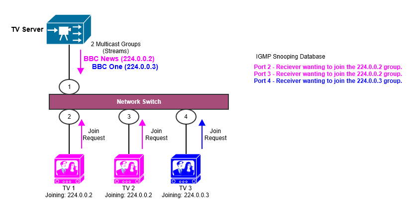
When the TVs want to join a group, they issue a join request to the network, the IGMP Snooper on the network switch identifies this join request (i.e. snoops on it) and ensures that rather than flooding all multicast streams out of all ports, it instead ensures that only ports that are requesting it, get it. So in the case of the 224.0.0.2 Multicast Group, it sends it out Port 2 and Port 3 which go to the receivers who have requested it, TV1 and TV2 in this case. TV3 which has requested to join the 224.0.0.3 Multicast Group does not get the 224.0.0.2 stream, but instead only gets the stream it has requested i.e. 224.0.0.3 and that is sent out of Port 4; and conversely TV1 and TV2 (i.e. Ports 2 and 3) don’t get TV3’s stream (224.0.0.2).
That in a nutshell is the IGMP snooping process, however the IGMP snooping also requires another key role and that is the IGMP querier, which is discussed in the next section called “IGMP Querier”.
IGMP Snooping Modes
There are three different IGMP snooping modes:
- Normal leave: This is the default mode. In this mode, the switch will wait for a certain amount of time (200 to 6348800 milliseconds) for an IGMP report before removing an IGMP snooping membership entry when an IGMP leave is received on the port from a multicast client.
- Fast leave: In this mode, the switch will send out an IGMP Group-Specific Query (GSQ) message immediately after receiving an IGMP leave report message. This will help to speed up the leave process.
- Immediate leave: In this mode, the switch will remove the port from its multicast forwarding table immediately after receiving an IGMP leave report message. This is the most efficient mode, but it can also cause problems if there are multiple clients on the port that are still using the multicast group.
IGMP Snooping with Proxy
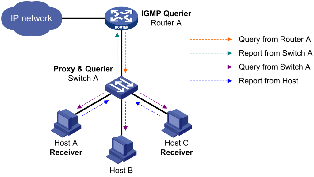
You can configure the IGMP snooping proxying function on an edge device to reduce the number of IGMP reports and leave messages sent to its upstream device.
Basically the IGMP Querier sees Host A, Host B and Host C as only Switch A which is acting on behalf of (i.e. a proxy) of the Hosts, so rather than 3 reports going back, only 1 goes back to the IGMP Querier.
IGMP Querier
The IGMP Querier is a role that listens for these IGMP join requests and determines which receivers (clients) want to receive specific multicast streams. The IGMP querier sends IGMP queries to prompt network switches to report their multicast group memberships (i.e. their downstream recievers/clients), ensuring that multicast traffic only reaches relevant parts of the network. To illustrate, it is unnecessary for a particular multicast group/stream being sent to a downstream switch, if there are no receivers requesting that particular multicast group/stream from that downstream switch; the IGMP querier ensures that this is the case and network resources are not being wasted on sending traffic to places it is not required.
![]() One Multicast IGMP querier is required per VLAN/Layer 2 segment for reliable Multicast services.
One Multicast IGMP querier is required per VLAN/Layer 2 segment for reliable Multicast services.
Typically, a multicast router (Layer 3 device) is present in a VLAN/Layer 2 segment, this would normally be the default gateway (unicast router); in which case no specific configuration of an IGMP querier is required, the multicast router would assume this role and act as the IGMP Querier for that VLAN/Layer 2 segment.
![]() However, if there is no dedicated multicast router (such as an isolated VLAN/Layer 2 segment), an IGMP Querier must be manually assigned to an appropriate network switch to provide this role.
However, if there is no dedicated multicast router (such as an isolated VLAN/Layer 2 segment), an IGMP Querier must be manually assigned to an appropriate network switch to provide this role.
Example: Without an IGMP Querier Present
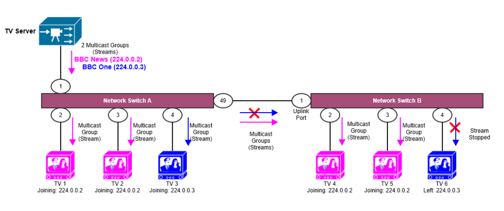
Let’s revisit the example of a single VLAN/Layer 2 segment, however this time we have two network switches (Switch A and Switch B), and 6 TV clients (3 on Switch A, and 3 on Switch B), the TV server remains in its original location.
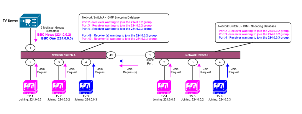
The Diagram 2 above shows the network, but without an IGMP querier defined, both Switch A and Switch B have IGMP snooping enabled and are seeing the join requests, and these join requests ensure that both Network Switch A and Network Switch B are distributing the multicast groups/streams to the correct ports based on their request.
However, there is a problem, without a IGMP querier defined for the VLAN/Layer 2 segment there is nothing to check to see that all the receivers (TVs) still want to receive the multicast group/stream after they have joined, by default an Extreme Networks XOS (SwitchEngine) switch will time out any receivers within the cache if they have not updated their status within a particular timeout period, by default this is 5 minutes (300 seconds) can be seen as follows:
Slot-2 switchA.15 # show mcast cache
Snooping/MVR Cache Timeout: 300 sec

<Output removed for brevity>
The behaviour observed in this situation would be that the receivers (clients) would successfully join a multicast group/stream, but after around 5 minutes the stream would either stop or pause because the IGMP snooping of the switch would incorrectly think that the reciever/client doesn’t want the stream any more because it has not seen a IGMP Membership Report telling it to continue providing that stream to that network port.
The reason for this being that maintaining the list/cache of interested multicast receivers/clients on the network is the role of the IGMP querier; which in this case does not exist!
Example: With an IGMP Querier Present
The IGMP Querier sends out periodic IGMP General Query messages to all multicast receivers (clients) in the network. These queries ask the network switches and receivers (clients) whether they are still interested in receiving multicast traffic for specific groups. When a receiver wants to remain part of a multicast group, it responds with an “IGMP Membership Report”. If a receiver (client) no longer needs the multicast traffic, it can either send a Leave Group message or simply stop responding to queries; which means at the end of the IGMP Snooping/MVR timeout period (around 5 minutes) the stream will no longer be sent to that receiver (client).
The process allows the IGMP Querier to keep an up-to-date list of receivers (clients) that are subscribed to the multicast groups and thus able to optimise the flows of these network streams across the network.
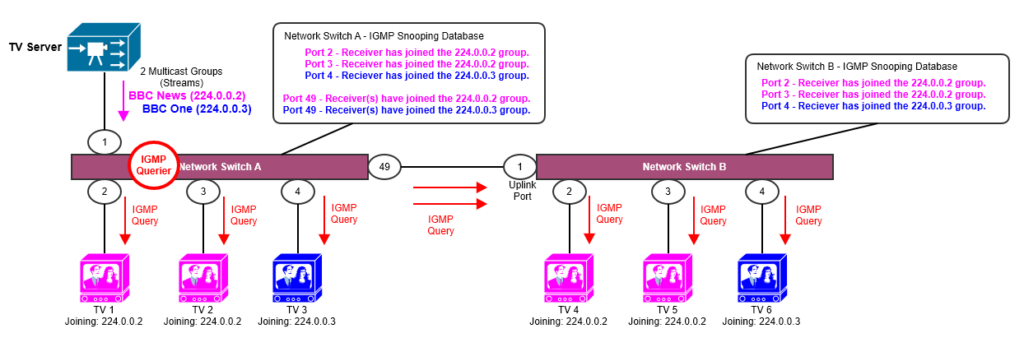
So looking at our example (Diagram 3), we have configured Network Switch A as the IGMP Querier for that particular VLAN/Layer 2 segment, so this switch will be responsible for keeping this list of receivers (clients) up to date. We have decided that Network Switch A was best placed to be the IGMP Querier for this VLAN/Layer 2 segment based on its proximity to the TV Server, but any other switch could be used depending on the network configuration. Full details of this configuration, and aspects of how elections can be found in the Extreme Networks Multicast in Action section below.
We have 6 TVs that after successfully joining the Multicast Groups (streams) are now all happily streaming BBC News and BBC One, the IGMP Querier is now present on Network Switch A, and every 125 seconds (i.e. less than half the timeout) sends an IGMP Query to all the receivers (clients) across the VLAN/Layer 2 segment to keep the list up to date.
Because the list of receivers (clients) is periodically being updated/refreshed based on the responses to the IGMP queries the IGMP Querier is generating, we no longer have the issue that receivers’ (clients’) streams are being incorrectly “pruned” because no update to the list is being performed.
Now in Diagram 4, Let’s say someone finishes watching TV6, so they just turn it off, the next time the IGMP Querier performs an IGMP query to all the known receivers (clients), it gets no response from TV6, so removes that from the list of receivers for the 224.0.0.3 group, so that traffic is no longer sent out of Port 4 of Network Switch B, what also happens here is that the Network Switch B being that it now has no receivers for the network group (stream) 224.0.0.3, signals that it no longer needs that network group either.
At this point only the 224.0.0.2 network group is being used on Network Switch B, so the 224.0.0.3 network group (stream) is not being sent across the uplink between Network Switch A and Network Switch B; thus saving network resources.
In the next section we’ll show how this is practically implemented and monitored on Extreme Networks XOS (SwitchEngine) switches.
Extreme Networks Multicast in Action
The following illustrates multicast in a VLAN/Layer 2 using some sample outputs and commands based on a scenario similar to the ones given above; the examples are provided in XOS (SwitchEngine) only.
How to enable IGMP Snooping
IGMP Snooping should be enabled by default, if it is not, you can enable on the switch as follows:
enable igmp snoopingHow to configure the IGMP Querier, and how to find the switch that is the IGMP Querier
IGMP snooping expects at least one device on every VLAN to periodically generate IGMP query messages. Without an IGMP querier, the switch eventually stops forwarding IP multicast packets to any port, because the IGMP snooping entries time out, based on the value specified in host_timeout or router_timeout. Each Network/VLAN would need a separate IGMP querier, Just by assigning an IP address to the VLAN would start the switch to act as IGMP querier.
Let’s take our example network, we have Network Switch A and Network Switch B, connected to Network Switch A is a Router, it’s not a multicast enabled router, in this particular example we just have a single VLAN/Layer 2 Segment (called “nc-tv”) within which the TV Server, the 6 TVs sit. IGMP Snooping has been enabled on Network Switch A and Network Switch B.
But we’ve not yet assigned the IGMP Querier.
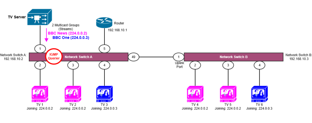
Our IP range for this particular VLAN/Layer 2 Segment is 192.168.10.0/24, each VLAN/Layer 2 Segment needs its own IGMP Querier, in our case we want to enable this on Network Switch A.
To enable the IGMP Querier it is as simple as adding an IP address to the VLAN on Network Switch A
configure vlan nc-tv ipaddress 192.168.10.2The IGMP Querier will always be the interface with the lowest IP that is IGMP capable within the VLAN/Layer 2 Segment, in this case the default gateway (router) is 192.168.10.1, but this is not IGMP capable, therefore Network Switch A will be elected as the IGMP Querier being it has the lowest IP in the VLAN/Layer 2 that is IGMP capable, of course Network Switch B is also IGMP capable, but its IP address is 192.168.10.3 so higher than Switch A, thus it would only elect as the IGMP Querier if Network Switch A were to become unavailable.
switchA # show igmp vlan nc-tv
Query Interval    :    125 sec
Max Response Time :     10 sec
Last Member Query :      1 sec
Robustness        :      2

Interface on VLAN nc-tv is enabled and up.
    inet 192.168.10.2/24
    Locally registered multicast addresses:
        224.0.0.2          224.0.0.22
    Learned multicast addresses(Last Querier=192.168.10.2):
        239.100.2.2        239.100.2.7        239.255.255.250
        224.0.0.251

        s = static igmp member

    Querier UpTime: 5 days 2 hours 39 minutes 24 seconds

    Flags:
        IP Fwding  NO       IPmc Fwding  NO            IGMP YES
         IGMP Ver  V2          Snooping YES     Proxy Query YES
      XmitRtrAlrt YES     RcvRtrAlrtReq  NO
Examining the output of Network Switch B we can see that Network Switch B thinks the IGMP Querier for the VLAN/Layer 2 Segment is Network Switch A which is as expected; we can also see the Network Switch B VLAN interface has its IP address set, but has not been elected as the IGMP Querier for this VLAN/Layer 2 segment.
switchB # show igmp vlan nc-tv
Query Interval    :    125 sec
Max Response Time :     10 sec
Last Member Query :      1 sec
Robustness        :      2

Interface on VLAN nc-tv is enabled and up.
    inet 192.168.10.3/24
    Locally registered multicast addresses:

    Learned multicast addresses(Last Querier=192.168.10.2):
        224.0.0.2          224.0.0.22         239.100.2.2
        239.100.2.7        239.255.255.250    224.0.0.251

        s = static igmp member

    Querier UpTime: 5 days 2 hours 40 minutes 56 seconds

    Flags:
        IP Fwding  NO       IPmc Fwding  NO            IGMP YES
         IGMP Ver  V2          Snooping YES     Proxy Query YES
      XmitRtrAlrt YES     RcvRtrAlrtReq  NO
Show IGMP Configuration
To show the current configuration, you can use:
show igmpLooking into the output below, you can see that we are using IGMP version 2, we have 4 learned Multicast Addresses (nLeMA), and none of the VLANs have Multicast forwarding enabled, you would see this if the switch was also the router for that VLAN/Layer 2 Segment.
Slot-1 wtgc-edge-ser20-resc-c.1 # show igmp

VLAN                 IP Address           Flags     nLRMA  nLeMA IGMPver

Default              0.0.0.0        / 0   ---izpt-      0      0       2
edge-mgmt            172.16.15.16   /24   U--izpt-      2      1       2
nc-av                0.0.0.0        / 0   U--izpt-      0      0       2
nc-tv                192.168.255.253/30   U--izpt-      2      4       2
nltemp               0.0.0.0        / 0   U--izpt-      0      0       2
tv                   0.0.0.0        / 0   U--izpt-      0      0       2

Flags: (f) Forwarding Enabled, (i) IGMP Enabled
       (m) Multicast Forwarding Enabled, (p) IGMP Proxy Query Enabled
       (r) Receive Router Alert Required (t) Transmit Router Alert
       (U) Interface Up, (z) IGMP Snooping Enabled

       (nLeMA) Number of Learned Multicast Addresses
       (nLRMA) Number of Locally Registered Multicast Addresses
How to determine where the Multicast Source is
It’s not immediately straightforward to find the port, but you can find the Sender of network groups, let’s use our example network above, we have the VLAN “nc-tv”, running this command will show the sender IP:
show igmp snooping vlan nc-tvThe output can be very large, but here is a snippet to illustrate:
Router Timeout                :    260 sec
Host Timeout                  :    260 sec
Igmp Snooping Fast Leave Time :   1000 ms

VLAN nc-tv            (3874) Snooping=Enabled
    Group           Sender          Age
    239.100.1.1     10.255.68.12    71
    239.100.3.1     10.255.68.12    66
    239.100.5.1     10.255.68.12    57
    239.100.1.2     10.255.68.12    43
    239.100.1.3     10.255.68.12    71
    239.100.5.3     10.255.68.12    71

< Content Removed for Brevity >
As we can see the Sender is 10.255.68.12, from that we can then track down it’s MAC address, then from that which switch port it is connected to.
How to determine where Multicast Receivers (Clients) are (and what Multicast group/stream they are using)
There a few ways of doing this, two examples are given below; with a third for additional information.
Example 1
To show all the snooped entries for the “nc-tv” VLAN.
show igmp snooping vlan nc-tvThen look for the bottom part of the output that shows the Subscribed i.e. Network Group (Stream) to Host (Receiver) mapping, as you can see here there is a device on Port 1:3, it has an IP address 10.255.68.120, and has joined two streams: 239.100.2.2 and 239.255.255.250, one is likely a TV channel (probably 239.100.2.2) and the other 239.255.255.250 is probably a control stream or EPG (Electronic Programme Guide).
< Content Removed for Brevity >

Port   Host            Subscribed        Age    Group-Limit
    1:3    10.255.68.120   239.100.2.2       41     0
    1:3    10.255.68.120   239.255.255.250   39     0
    1:5    10.255.68.27    239.100.2.2       36     0
    1:5    10.255.68.27    239.255.255.250   36     0
    1:7    10.255.68.23    239.100.2.2       38     0
    1:7    10.255.68.23    239.255.255.250   35     0
    1:9    10.255.68.25    239.100.2.2       41     0

< Content Removed for Brevity >
Example 2
The second example is using a more up-to-date command.
show mcast cacheYou can be more specific by including some filters, for example the below will query for all the Network Groups (Streams) the cache knows about from the Sender (Source) 10.255.68.12.
show mcast cache group 239.100.0.0/16 source 10.255.68.12Example 3
Let’s examine the following output from a switch, looking specifically at our “nc-tv” VLAN, we can see that there are 205 Senders, which means there are 205 streams available within that VLAN for Receivers (clients) to use, we can also see that the ports 1:3, 1:5, 1:7 etc. are using the multicast streams.
switchA # show igmp snooping
Igmp Snooping Flag            : forward-all-router
Igmp Snooping Flood-list      : none
Igmp Snooping Proxy           : Enable
Igmp Snooping Filters         : per-port

Vlan             Vid  Port   #Senders #Receivers Router Enable
--------------------------------------------------------------
Default          4000        0                           Yes
edge-mgmt        886         1                           Yes
                      1:49             0          Yes
nc-av            1945        12                          Yes
                      1:49             0          Yes
nltemp           4086        0                           Yes
tv               299         3                           Yes
                      1:49             0          Yes
nc-tv            3874        205                         Yes
                      1:3              2          No
                      1:5              2          No
                      1:7              2          No
                      1:9              2          No
                      1:11             2          No
                      1:13             2          No
SSM-Map
The PIM-SSM feature requires all IGMP hosts to send IGMPv3 reports. Where you have an IGMPv2 host, this can create a compatibility problem. In particular, the reports from an IGMPv2 host contain a group multicast address but do not contain source addresses. The IGMPv3 reports contain both the group multicast address and one or more source addresses. This feature converts IGMPv2 reports into IGMPv3 reports through use of the ip igmp ssm-map command and a properly configured ACL.
Let’s say our IGMP TV Server (172.16.8.1) only supports IGMPv2, and is putting out a multicast streams/network groups within this range: 232.1.1.0/24. The following example configures an IGMP-SSM mapping for the range of multicast IP addresses at 232.1.1.0/24 originating from IP host 172.16.8.1:
configure igmp ssm-map add 232.1.1.0/24 172.16.8.1Additional Information
- https://extreme-networks.my.site.com/ExtrArticleDetail?an=000083173
- https://extreme-networks.my.site.com/ExtrArticleDetail?an=000102305
- https://extreme-networks.my.site.com/ExtrArticleDetail?an=000080842 (How to configure switch as IGMP querier)
- https://community.extremenetworks.com/t5/extremeswitching-exos-switch/multicast-communication-on-l2-vlan/td-p/33326/page/2
- https://extreme-networks.my.site.com/ExtrArticleDetail?an=000083173
1 thought on “Multicast – IGMP Snooping and IGMP Querier – Sender and Reciever(s) in same VLAN/Layer 2 Segment”