
The AWS Transit Gateway can be used to join the networking of many VPCs (in the same or different AWS Accounts) within the same region together to facilitate communication, it may also be used in conjunction with DX (Direct Connect) or Site-to-Site VPNs to provide connectivity to other Cloud Platforms but additionally to on-premise networks (and data centres).
The example below demostrates how to create a simple Transit Gateway (TGW) environment with 2 VPCs connected via a Site-to-Site VPN to an on-premise network (firewalled by a Palo Alto Firewall), where routes are exchanged between the AWS TGW and on-premise network by use of the BGP routing protocol. The example also demostrates how this infrastructure can be deployed by use of Terraform, although a small bootstrapped environment is created using AWS Cloudformation to maintain, persist and lock the Terraform “state” to allow ongoing administration of the deployed infrastructure.
The example assumes you have a working knowledge of how to connect to the AWS CLI, how to use AWS Cloudformation and how to use Terraform; additionally how a Palo Alto Firewall works.
Terraform Template (with AWS Cloudformation bootstrap) can be found in my github: https://github.com/tristanhself/general/tree/master/aws/tgw-egress-vpn
Assumptions
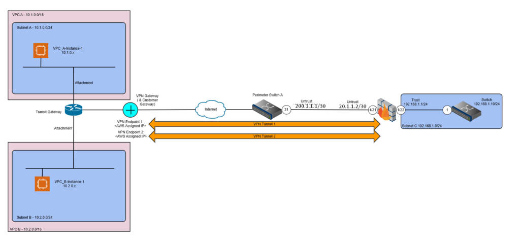
These instructions assume you have a Palo Alto Firewall setup (as per the diagram below) with a “Trust” and a “Untrust”, effectively a physical interface that faces the Internet (Untrust) and a physical interface that faces the internal network (Trust). It also assumes you have things like Interface Management Profiles set so you can at least ping things to test each stage of the configuration.
It also assumes that the Palo Alto Firewall has been configured with a default route to allow traffic outbound and some Security Policies (firewall rules) that permit both outbound traffic but also inbound, along with the relevant NAT configuration (for IPV4).
Example Topology Diagram
Bootstrapping the Environment
The following is provided for reference only and is required to first bootstrap the Terraform environment by creating the required AWS S3 Bucket and AWS DynamoDB Table to store and lock the Terraform State; once bootstrapped all further configuration changes are made via Terraform.
![]() You only need to bootstrap the environment once to create the required objects to support the use of Terraform. Terraform State is stored within an S3 Bucket, the Terraform Lock File is stored within the AWS DynamoDB, the bootstrap creates these for you, so you don’t need to create them manually.
You only need to bootstrap the environment once to create the required objects to support the use of Terraform. Terraform State is stored within an S3 Bucket, the Terraform Lock File is stored within the AWS DynamoDB, the bootstrap creates these for you, so you don’t need to create them manually.
Pre-requisites
- Access to the AWS console for the relevant account.
- Terraform and git installed and in your path
Prepare the Infrastructure
1. Clone this repo.
2. Run the following AWS Cloudformation Template to bootstrap the AWS resources needed to manage the AWS resources with Terraform safely. You’ll need to be logged into an AWS account already.
aws cloudformation create-stack --template-body file://bootstrap.yaml --stack-name tgw-egress-vpn --capabilities CAPABILITY_NAMED_IAM3. Run the following Terraform commands to initalise your Terraform environment, (any) existing Terraform state will be retrieved from the AWS S3 Terraform State Bucket.
terraform initYour Terraform environment is now ready for use.
Part 1 – Configuring the Example AWS VPC and Transite Gateway (TGW) Infrastructure (using Terraform)
Step 1 – Deploy the AWS Environment via Terraform
Once you have the environment bootstrapped, you can deploy the infrastructure via Terraform with:
terraform planThen if all looks good:
terraform applyWait for the infrastructure to deploy, the Terraform will provide an output of the VPN endpoint IP Addresses and the IP addresses of two (2) test EC2 instances, make a note of these.
Step 2 – Obtain VPN Information (Shared Keys, Cipher Types etc.)
Within the AWS Console perform the following steps:
1. Go to AWS VPC.
2. Under Virtual Private Network on the left hand pane, click Site-to-Site VPN.
3. Click on the VPN Connection created by the Terraform, should be “TGW-VPN-1”, then click on “Download Configration”; from there download the configuration as the most up to date version of PANOS.
4. Open the text file and obtain the relevant details, specifically:
- Tunnel 1 Shared Secret Key
- Tunnel 2 Shared Secret Key
You should also ensure you have the relevant Cipher sets for the phase 1 (IKE) and phase 2 (IPSEC) tunnels, oddly the download configuration won’t give you these, those you’ll need to get as follows:
5. Click on the VPN Connection created by the Terraform, should be “TGW-VPN-1”, then click on Tunnel Details (tab), you’ll see the relevant configurations for cipher types etc, which you’ll need to configure the Palo Alto end of the VPN shortly, for example:
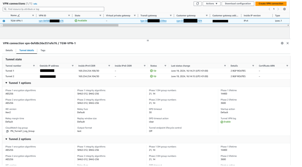
Essentially the information on the Tunnel Details (tab) gives you all the information you need to setup the Palo Alto Firewall side of the VPN.
Part 2 – Configure Palo Alto Firewall for Site-to-Site VPN Termination
The steps below demonstrate how to configure the Palo Alto Firewall. You’ll need to create two IPSec Tunnels, these instructions are written according to that, where by there are two “paths” from the on-premise site to the AWS cloud.
Step 1 – Internet Key Exchange (IKE) Configuration
IKE Crypto
set network ike crypto-profiles ike-crypto-profiles AWS-IKE-CRYPTO hash [ sha256 sha512 ]
set network ike crypto-profiles ike-crypto-profiles AWS-IKE-CRYPTO dh-group [ group14 group2 ]
set network ike crypto-profiles ike-crypto-profiles AWS-IKE-CRYPTO encryption [ aes-128-cbc aes-256-cbc ]
set network ike crypto-profiles ike-crypto-profiles AWS-IKE-CRYPTO lifetime hours 8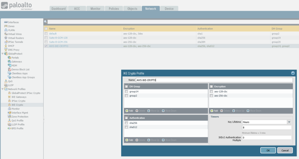
Step 2 – IPSec Configuration
IPSEC Crypto
set network ike crypto-profiles ipsec-crypto-profiles AWS-IPSEC-CRYPTO esp authentication [ sha256 sha512 ]
set network ike crypto-profiles ipsec-crypto-profiles AWS-IPSEC-CRYPTO esp encryption [ aes-256-cbc aes-256-gcm ]
set network ike crypto-profiles ipsec-crypto-profiles AWS-IPSEC-CRYPTO lifetime hours 1
set network ike crypto-profiles ipsec-crypto-profiles AWS-IPSEC-CRYPTO dh-group group14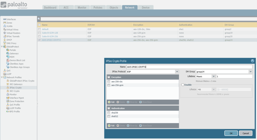
IKE Gateway
Utilising the previously created IKE Gateway and IPSEC Crypto
set network ike gateway AWS-TGW-VPN-1 authentication pre-shared-key key <PRESHAREDKEYHERE!!!>
set network ike gateway AWS-TGW-VPN-1 protocol ikev1 dpd enable yes
set network ike gateway AWS-TGW-VPN-1 protocol ikev2 dpd enable yes
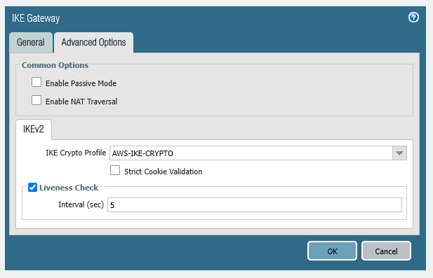
set network ike gateway AWS-TGW-VPN-1 protocol ikev2 ike-crypto-profile AWS-IKE-CRYPTO
set network ike gateway AWS-TGW-VPN-1 protocol version ikev2
set network ike gateway AWS-TGW-VPN-1 local-address ip 200.1.1.2/30
set network ike gateway AWS-TGW-VPN-1 local-address interface ethernet1/21
set network ike gateway AWS-TGW-VPN-1 protocol-common nat-traversal enable no
set network ike gateway AWS-TGW-VPN-1 protocol-common fragmentation enable no
set network ike gateway AWS-TGW-VPN-1 peer-address ip 18.10.143.81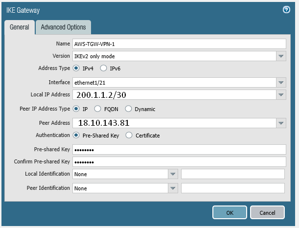
set network ike gateway AWS-TGW-VPN-2 authentication pre-shared-key key <PRESHAREDKEYHERE!!!>
set network ike gateway AWS-TGW-VPN-2 protocol ikev1 dpd enable yes
set network ike gateway AWS-TGW-VPN-2 protocol ikev2 dpd enable yes
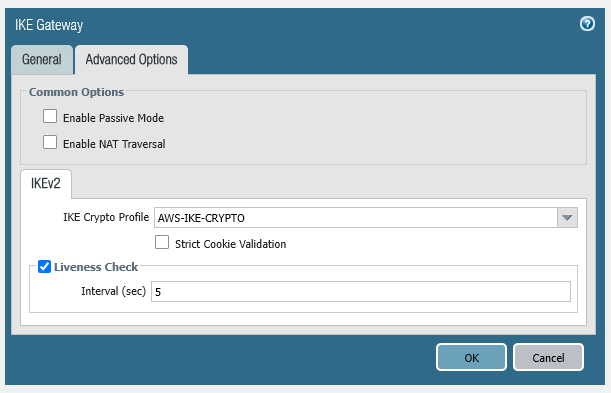
set network ike gateway AWS-TGW-VPN-2 protocol ikev2 ike-crypto-profile AWS-IKE-CRYPTO
set network ike gateway AWS-TGW-VPN-2 protocol version ikev2
set network ike gateway AWS-TGW-VPN-2 local-address ip 200.1.1.2/30
set network ike gateway AWS-TGW-VPN-2 local-address interface ethernet1/21
set network ike gateway AWS-TGW-VPN-2 protocol-common nat-traversal enable no
set network ike gateway AWS-TGW-VPN-2 protocol-common fragmentation enable no
set network ike gateway AWS-TGW-VPN-2 peer-address ip 18.10.87.81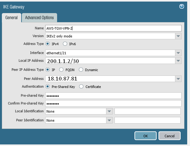
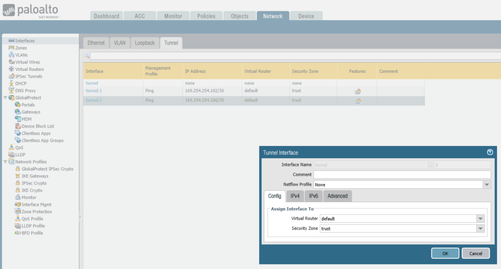
Step 3 – Tunnel Interface Configuration
Create the tunnel interfaces
notice the point to point IP addresses which must match the subnet used by AWS, i.e. if the network used is 169.254.254.100/30, then the AWS end will likely be: 169.254.254.101, so your Palo Alto Firewall end needs to be: 169.254.254.102, i.e. the IP on that tunnel interface.
set network interface tunnel units tunnel.1 ip 169.254.254.102/30
set network interface tunnel units tunnel.1 mtu 1427
set network interface tunnel units tunnel.1 interface-management-profile Ping
set network interface tunnel units tunnel.2 ip 169.254.254.106/30
set network interface tunnel units tunnel.2 mtu 1427
set network interface tunnel units tunnel.2 interface-management-profile PingAssociate Tunnel Interfaces to Trust Zone
Associate tunnel interface to the zone, in this example terminating into the “trust” zone, but in production you’d potentially want to terminate into a different zone so you can apply access restrictions between your internal networks and the networks at AWS accessible via the VPN.
set zone trust network layer3 [ ethernet1/22 tunnel.1 tunnel.2 ]
Associate Tunnel Interfaces to a Virtual Router
We are using the “default” Virtual Router, you may choose to do this differently in a production environment.
set network virtual-router default interface [ ethernet1/21 ethernet1/22 tunnel.1 tunnel.2 ]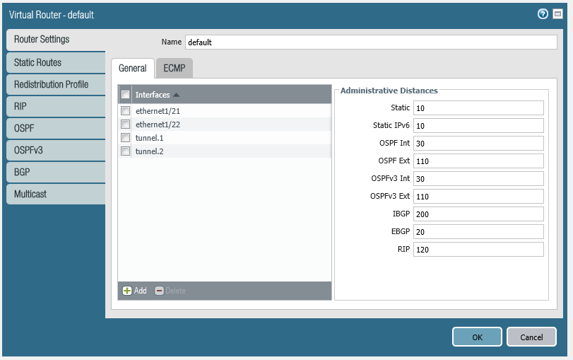
Create Monitor
set network profiles monitor-profile AWSVPN-MONITOR
set network profiles monitor-profile AWSVPN-MONITOR interval 3
set network profiles monitor-profile AWSVPN-MONITOR threshold 5
set network profiles monitor-profile AWSVPN-MONITOR action wait-recover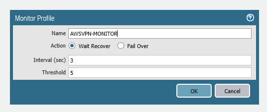
Create IPSec VPN Tunnels
You now need to create the VPN tunnels, which will utilise the previously created IKE Gateway and IPSEC Crypto definitions.
set network tunnel ipsec AWS-TGW-VPN-1 auto-key ike-gateway AWS-TGW-VPN-1
set network tunnel ipsec AWS-TGW-VPN-1 auto-key ipsec-crypto-profile AWS-IPSEC-CRYPTO
set network tunnel ipsec AWS-TGW-VPN-1 tunnel-monitor enable yes
set network tunnel ipsec AWS-TGW-VPN-1 tunnel-monitor destination-ip 169.254.254.101
set network tunnel ipsec AWS-TGW-VPN-1 tunnel-monitor tunnel-monitor-profile AWSVPN-MONITOR
set network tunnel ipsec AWS-TGW-VPN-1 tunnel-interface tunnel.1
set network tunnel ipsec AWS-TGW-VPN-1 disabled no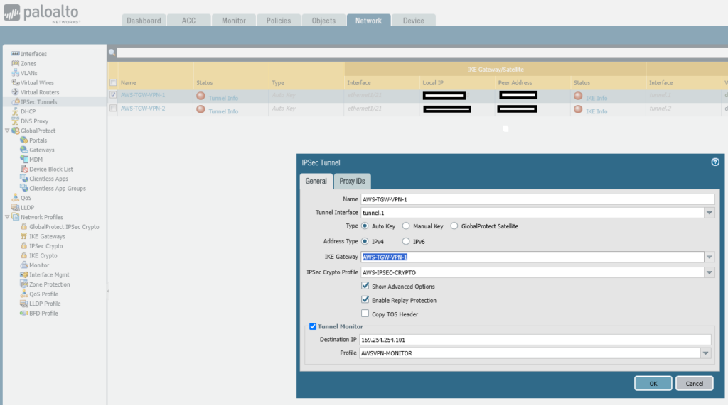
set network tunnel ipsec AWS-TGW-VPN-2 auto-key ike-gateway AWS-TGW-VPN-2
set network tunnel ipsec AWS-TGW-VPN-2 auto-key ipsec-crypto-profile AWS-IPSEC-CRYPTO
set network tunnel ipsec AWS-TGW-VPN-2 tunnel-monitor enable yes
set network tunnel ipsec AWS-TGW-VPN-2 tunnel-monitor destination-ip 169.254.254.105
set network tunnel ipsec AWS-TGW-VPN-2 tunnel-monitor tunnel-monitor-profile AWSVPN-MONITOR
set network tunnel ipsec AWS-TGW-VPN-2 tunnel-interface tunnel.2
set network tunnel ipsec AWS-TGW-VPN-2 disabled no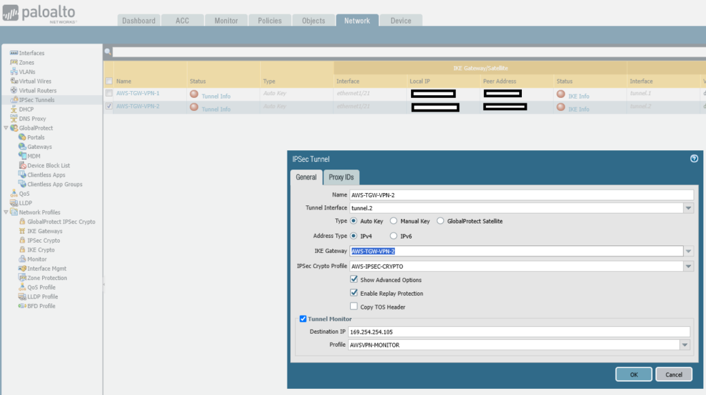
Step 4 – BGP Configuration
The BGP configuration is added so that the on-premise end uses the AS 65001, while the AWS end uses an AWS assigned AS number. Routes are exchanged between the TGW at the AWS end and the on-premise Palo Alto when learnt by either end, that way no static route configurations are needed to deal with on-boarding or off-boarding of networks.
All this configuraiton happens on the Virtual Router (VR).
Configure BGP on Virtual Router
set network virtual-router default protocol bgp enable yes
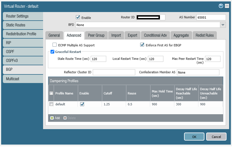
set network virtual-router default protocol bgp dampening-profile default cutoff 1.25
set network virtual-router default protocol bgp dampening-profile default reuse 0.5
set network virtual-router default protocol bgp dampening-profile default max-hold-time 900
set network virtual-router default protocol bgp dampening-profile default decay-half-life-reachable 300
set network virtual-router default protocol bgp dampening-profile default decay-half-life-unreachable 900
set network virtual-router default protocol bgp dampening-profile default enable yes
set network virtual-router default protocol bgp routing-options graceful-restart enable yes
set network virtual-router default protocol bgp global-bfd profile None
set network virtual-router default protocol bgp router-id 200.1.1.2
set network virtual-router default protocol bgp local-as 65001
set network virtual-router default protocol bgp install-route yes
set network virtual-router default protocol bgp allow-redist-default-route yes
set network virtual-router default protocol rip enable no
set network virtual-router default protocol ospf enable no
set network virtual-router default protocol ospfv3 enable no
set network virtual-router default ecmp algorithm ip-moduloThe configuration above is not the full configuration for the Virtual Router, it is only the basic BGP configuration, things like the default route for outbound traffic and adding of the interfaces to the VR is assumed to have already taken place.
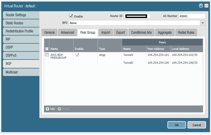
Configure BGP Peer Group
The BGP Peer Group contains the two peers, i.e. a peer down each tunnel.
set network virtual-router default protocol bgp peer-group AWS-BGP-PEERGROUP type ebgp remove-private-as yes
set network virtual-router default protocol bgp peer-group AWS-BGP-PEERGROUP type ebgp import-nexthop original
set network virtual-router default protocol bgp peer-group AWS-BGP-PEERGROUP type ebgp export-nexthop resolve
set network virtual-router default protocol bgp peer-group AWS-BGP-PEERGROUP peer Tunnel1 connection-options incoming-bgp-connection remote-port 0
set network virtual-router default protocol bgp peer-group AWS-BGP-PEERGROUP peer Tunnel1 connection-options incoming-bgp-connection allow yes
set network virtual-router default protocol bgp peer-group AWS-BGP-PEERGROUP peer Tunnel1 connection-options outgoing-bgp-connection local-port 0
set network virtual-router default protocol bgp peer-group AWS-BGP-PEERGROUP peer Tunnel1 connection-options outgoing-bgp-connection allow yes
set network virtual-router default protocol bgp peer-group AWS-BGP-PEERGROUP peer Tunnel1 connection-options multihop 0
set network virtual-router default protocol bgp peer-group AWS-BGP-PEERGROUP peer Tunnel1 connection-options keep-alive-interval 10
set network virtual-router default protocol bgp peer-group AWS-BGP-PEERGROUP peer Tunnel1 connection-options open-delay-time 0
set network virtual-router default protocol bgp peer-group AWS-BGP-PEERGROUP peer Tunnel1 connection-options hold-time 30
set network virtual-router default protocol bgp peer-group AWS-BGP-PEERGROUP peer Tunnel1 connection-options idle-hold-time 15
set network virtual-router default protocol bgp peer-group AWS-BGP-PEERGROUP peer Tunnel1 connection-options min-route-adv-interval 30
set network virtual-router default protocol bgp peer-group AWS-BGP-PEERGROUP peer Tunnel1 subsequent-address-family-identifier unicast yes
set network virtual-router default protocol bgp peer-group AWS-BGP-PEERGROUP peer Tunnel1 subsequent-address-family-identifier multicast no
set network virtual-router default protocol bgp peer-group AWS-BGP-PEERGROUP peer Tunnel1 local-address ip 169.254.254.102/30
set network virtual-router default protocol bgp peer-group AWS-BGP-PEERGROUP peer Tunnel1 local-address interface tunnel.1
set network virtual-router default protocol bgp peer-group AWS-BGP-PEERGROUP peer Tunnel1 peer-address ip 169.254.254.101
set network virtual-router default protocol bgp peer-group AWS-BGP-PEERGROUP peer Tunnel1 bfd profile Inherit-vr-global-setting
set network virtual-router default protocol bgp peer-group AWS-BGP-PEERGROUP peer Tunnel1 max-prefixes 5000
set network virtual-router default protocol bgp peer-group AWS-BGP-PEERGROUP peer Tunnel1 enable yes
set network virtual-router default protocol bgp peer-group AWS-BGP-PEERGROUP peer Tunnel1 peer-as 64512
set network virtual-router default protocol bgp peer-group AWS-BGP-PEERGROUP peer Tunnel1 enable-mp-bgp no
set network virtual-router default protocol bgp peer-group AWS-BGP-PEERGROUP peer Tunnel1 address-family-identifier ipv4
set network virtual-router default protocol bgp peer-group AWS-BGP-PEERGROUP peer Tunnel1 enable-sender-side-loop-detection yes
set network virtual-router default protocol bgp peer-group AWS-BGP-PEERGROUP peer Tunnel1 reflector-client non-client
set network virtual-router default protocol bgp peer-group AWS-BGP-PEERGROUP peer Tunnel1 peering-type unspecified
set network virtual-router default protocol bgp peer-group AWS-BGP-PEERGROUP peer Tunnel2 connection-options incoming-bgp-connection remote-port 0
set network virtual-router default protocol bgp peer-group AWS-BGP-PEERGROUP peer Tunnel2 connection-options incoming-bgp-connection allow yes
set network virtual-router default protocol bgp peer-group AWS-BGP-PEERGROUP peer Tunnel2 connection-options outgoing-bgp-connection local-port 0
set network virtual-router default protocol bgp peer-group AWS-BGP-PEERGROUP peer Tunnel2 connection-options outgoing-bgp-connection allow yes
set network virtual-router default protocol bgp peer-group AWS-BGP-PEERGROUP peer Tunnel2 connection-options multihop 0
set network virtual-router default protocol bgp peer-group AWS-BGP-PEERGROUP peer Tunnel2 connection-options keep-alive-interval 10
set network virtual-router default protocol bgp peer-group AWS-BGP-PEERGROUP peer Tunnel2 connection-options open-delay-time 0
set network virtual-router default protocol bgp peer-group AWS-BGP-PEERGROUP peer Tunnel2 connection-options hold-time 30
set network virtual-router default protocol bgp peer-group AWS-BGP-PEERGROUP peer Tunnel2 connection-options idle-hold-time 15
set network virtual-router default protocol bgp peer-group AWS-BGP-PEERGROUP peer Tunnel2 connection-options min-route-adv-interval 30
set network virtual-router default protocol bgp peer-group AWS-BGP-PEERGROUP peer Tunnel2 subsequent-address-family-identifier unicast yes
set network virtual-router default protocol bgp peer-group AWS-BGP-PEERGROUP peer Tunnel2 subsequent-address-family-identifier multicast no
set network virtual-router default protocol bgp peer-group AWS-BGP-PEERGROUP peer Tunnel2 local-address ip 169.254.254.106/30
set network virtual-router default protocol bgp peer-group AWS-BGP-PEERGROUP peer Tunnel2 local-address interface tunnel.2
set network virtual-router default protocol bgp peer-group AWS-BGP-PEERGROUP peer Tunnel2 peer-address ip 169.254.254.105
set network virtual-router default protocol bgp peer-group AWS-BGP-PEERGROUP peer Tunnel2 bfd profile Inherit-vr-global-setting
set network virtual-router default protocol bgp peer-group AWS-BGP-PEERGROUP peer Tunnel2 max-prefixes 5000
set network virtual-router default protocol bgp peer-group AWS-BGP-PEERGROUP peer Tunnel2 enable yes
set network virtual-router default protocol bgp peer-group AWS-BGP-PEERGROUP peer Tunnel2 peer-as 64512
set network virtual-router default protocol bgp peer-group AWS-BGP-PEERGROUP peer Tunnel2 enable-mp-bgp no
set network virtual-router default protocol bgp peer-group AWS-BGP-PEERGROUP peer Tunnel2 address-family-identifier ipv4
set network virtual-router default protocol bgp peer-group AWS-BGP-PEERGROUP peer Tunnel2 enable-sender-side-loop-detection yes
set network virtual-router default protocol bgp peer-group AWS-BGP-PEERGROUP peer Tunnel2 reflector-client non-client
set network virtual-router default protocol bgp peer-group AWS-BGP-PEERGROUP peer Tunnel2 peering-type unspecified
set network virtual-router default protocol bgp peer-group AWS-BGP-PEERGROUP aggregated-confed-as-path yes
set network virtual-router default protocol bgp peer-group AWS-BGP-PEERGROUP soft-reset-with-stored-info no
set network virtual-router default protocol bgp peer-group AWS-BGP-PEERGROUP enable yes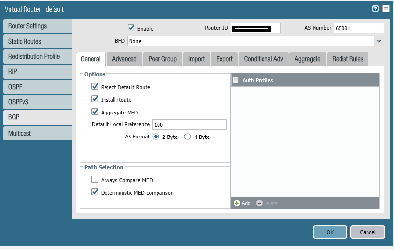
Step 5 – Advertise On-Premise Routes
In this particular example we are going to also advertise the default route up into the AWS TGW, so that the EC2 instances in the VPCs can communicate to the Internet by following the path: Local VPC Subnet Router → Transit Gateway (TGW) → VPN Tunnel (1 or 2) → On-Premise Palo Alto Firewall Virtual Router → Untrust Interface → Internet, so effectively “hairpinning” their Internet access via the on-premise firewall, in a real world production configuration you may not want to do this, and instead configure some local AWS end egress to allow Internet access direct from AWS.
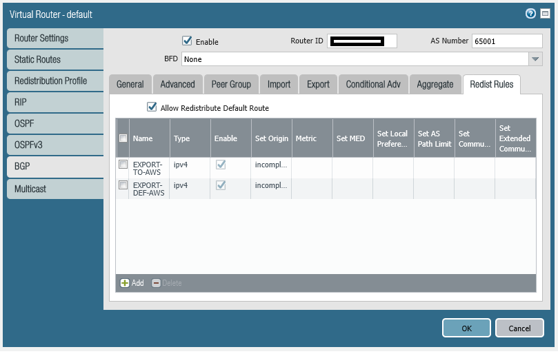
Connected Networks – Create Redistribution Profile and Restribution Rule
We’ll want to advertise our local on-premise network, i.e. 192.168.1.0 up the VPN via BGP to the Transit Gateway at AWS, so the TGW can learn the route and therefore allow traffic to flow up and down the VPN.
We first create the Redistribution Profile that advertises in this example just the connected network, you can of course include other networks in a more complicated setup which you wish to export to the AWS TGW via the VPN.
set network virtual-router default protocol redist-profile EXPORT-TO-AWS filter type connect
set network virtual-router default protocol redist-profile EXPORT-TO-AWS filter interface ethernet1/22
set network virtual-router default protocol redist-profile EXPORT-TO-AWS priority 2
set network virtual-router default protocol redist-profile EXPORT-TO-AWS action redist
Now we create a Redistribution Rule for this to advertise the connected networks.
set network virtual-router default protocol bgp redist-rules EXPORT-TO-AWS address-family-identifier ipv4
set network virtual-router default protocol bgp redist-rules EXPORT-TO-AWS route-table unicast
set network virtual-router default protocol bgp redist-rules EXPORT-TO-AWS enable yes
set network virtual-router default protocol bgp redist-rules EXPORT-TO-AWS set-origin incomplete
Default Route – Create Redistribution Profile and Restribution Rule
Your gateway can advertise a default route 0.0.0.0/0 to AWS VPC for which you would need to create a redistribution profile as follows, allow redistribution of default route and finally apply the redistribution profile under bgp.
![]() The “set network virtual-router default protocol bgp allow-redist-default-route yes” was set earlier.
The “set network virtual-router default protocol bgp allow-redist-default-route yes” was set earlier.
set network virtual-router default protocol redist-profile EXPORT-DEF-AWS filter type static
set network virtual-router default protocol redist-profile EXPORT-DEF-AWS filter destination 0.0.0.0/0
set network virtual-router default protocol redist-profile EXPORT-DEF-AWS priority 10
set network virtual-router default protocol redist-profile EXPORT-DEF-AWS action redist
set network virtual-router default protocol bgp redist-rules EXPORT-DEF-AWS address-family-identifier ipv4
set network virtual-router default protocol bgp redist-rules EXPORT-DEF-AWS route-table unicast
set network virtual-router default protocol bgp redist-rules EXPORT-DEF-AWS enable yes
set network virtual-router default protocol bgp redist-rules EXPORT-DEF-AWS set-origin incomplete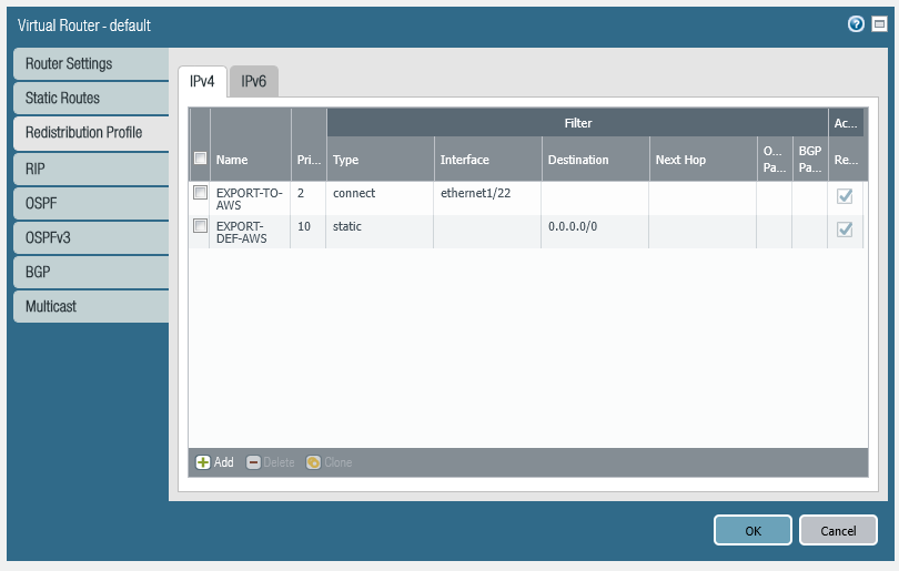
Step 6 – Testing the Routing (AWS TGW and VPN)
We at this point should have a working AWS TGW and VPN which is up and providing connectivity between the on-premise network and the AWS VPC(s) via the Site-to-Site VPN and Transit Gateway (TGW), we can now explore these with some basic tests.
Connectivity Examples
- EC2Instance1 in VPC A can ping EC2Instance2 in VPC B via TGW
- EC2Instance2 in VPC A can ping EC2Instance1 in VPC B via TGW.
- EC2Instance1 can ping on-premise loopback interface (192.168.1.10) on the test switch, via TGW, then via VPN, then via Palo Alto Firewall.
- EC2Instance2 can ping on-premise loopback interface (192.168.1.10) on the test switch, via TGW, then via VPN, then via Palo Alto Firewall.
- EC2Instance1 can ping Internet via TGW, then via VPN, then via Palo Alto Firewall then to the Internet.
- EC2Instance2 can ping Internet via TGW, then via VPN, then via Palo Alto Firewall then to the Internet.
- On-premise loopback interface (192.168.1.10) on the test switch, can ping EC2Instance1 via Palo Alto Firewall, via Site-to-Site VPN, then via TGW.
- On-premise loopback interface (192.168.1.10) on the test switch, can ping EC2Instance2 via Palo Alto Firewall, via Site-to-Site VPN, then via TGW.
- Loss of VPN Tunnel 1 (Tunnel 2 still operational) does not affect connectivity between AWS TGW (and VPCs) and On-Premise Network.
- Loss of VPN Tunnel 2 (Tunnel 1 still operational) does not affect connectivity between AWS TGW (and VPCs) and On-Premise Network.
Infrastructure Deep-Dive
The infrastructure consists of the two VPCs A and B, along with the Transit Gateway (TGW) and the on-premise Firewall and network (essentially VPC C in this scenario), each VPC has one Private Subnet. We’ll now explore the Terraform mark-up section by section.
Virtual Private Cloud (VPC)
We first create the VPCs, in this case we create two.
resource "aws_vpc" "VPC_A" {
  cidr_block       = "10.1.0.0/16"
  instance_tenancy = "default"

  tags = {
    Name = "VPC_A"
  }
}

resource "aws_vpc" "VPC_B" {
  cidr_block       = "10.2.0.0/16"
  instance_tenancy = "default"

  tags = {
    Name = "VPC_B"
  }
}
Subnets
We create one private subnet (i.e. no Internet access) in each VPC.
resource "aws_subnet" "VPC_A-Private-Subnet" {
  vpc_id                  = aws_vpc.VPC_A.id
  cidr_block              = "10.1.0.0/24"
  availability_zone       = "eu-west-2a"

  tags = {
    Name = "VPC_A-Private-Subnet"
  }
}

resource "aws_subnet" "VPC_B-Private-Subnet" {
  vpc_id                  = aws_vpc.VPC_B.id
  cidr_block              = "10.2.0.0/24"
  availability_zone       = "eu-west-2b"

  tags = {
    Name = "VPC_B-Private-Subnet"
  }
}
Route Tables
We then create a Route Table for each VPC and attach the it to the VPC, when then add a default route to each Route Table that points at the Transit Gateway.
resource "aws_route_table" "VPC_A-Private-RouteTable" {
  vpc_id   = aws_vpc.VPC_A.id

  tags = {
    Name         = "VPC_A-Private-RouteTable"
  }
}
resource "aws_route_table_association" "VPC_A-Private-RouteTable-Assoc" {
  subnet_id      = aws_subnet.VPC_A-Private-Subnet.id
  route_table_id = aws_route_table.VPC_A-Private-RouteTable.id
}
resource "aws_route" "VPC_A-Private-RouteTable-Route1" {
  route_table_id         = aws_route_table.VPC_A-Private-RouteTable.id
  destination_cidr_block = "0.0.0.0/0"
  transit_gateway_id     = aws_ec2_transit_gateway.TGW.id
}

resource "aws_route_table" "VPC_B-Private-RouteTable" {
  vpc_id   = aws_vpc.VPC_B.id

  tags = {
    Name         = "VPC_B-Private-RouteTable"
  }
}
resource "aws_route_table_association" "VPC_B-Private-RouteTable-Assoc" {
  subnet_id      = aws_subnet.VPC_B-Private-Subnet.id
  route_table_id = aws_route_table.VPC_B-Private-RouteTable.id
}
resource "aws_route" "VPC_B-Private-RouteTable-Route1" {
  route_table_id         = aws_route_table.VPC_B-Private-RouteTable.id
  destination_cidr_block = "0.0.0.0/0"
  transit_gateway_id     = aws_ec2_transit_gateway.TGW.id
}
Transit Gateway
We create the transit gateway, turning on route propagation that means that routes are automatically injected in from the attached VPCs and also from any attached VPN or DX connections.
resource "aws_ec2_transit_gateway" "TGW" {
  description                     = "Transit Gateway"
  default_route_table_association = "enable"
  default_route_table_propagation = "enable"
  vpn_ecmp_support = "enable"

  tags = {
    Name = "TGW"
  }
}
Transit Gateway Attachments
The VPC need to be attached to the Transit Gateway by way of an “attachment”.
resource "aws_ec2_transit_gateway_vpc_attachment" "VPC_A-TGW-Attachment" {
  subnet_ids         = [aws_subnet.VPC_A-Private-Subnet.id]
  transit_gateway_id = aws_ec2_transit_gateway.TGW.id
  vpc_id             = aws_vpc.VPC_A.id

  tags = {
    Name = "VPC_A-TGW-Attachment"
  }
}

resource "aws_ec2_transit_gateway_vpc_attachment" "VPC_B-TGW-Attachment" {
  subnet_ids         = [aws_subnet.VPC_B-Private-Subnet.id]
  transit_gateway_id = aws_ec2_transit_gateway.TGW.id
  vpc_id             = aws_vpc.VPC_B.id

  tags = {
    Name = "VPC_B-TGW-Attachment"
  }
}
Security Groups
We’ll be creating some test EC2 Instances, so we’ll create a Security Group for each.
resource "aws_security_group" "VPC_A-SecurityGroup-1" {
vpc_id = aws_vpc.VPC_A.id
ingress {
from_port = 22
to_port = 22
protocol = "tcp"
cidr_blocks = ["0.0.0.0/0"]
}
ingress {
from_port = 5001
to_port = 5001
protocol = "tcp"
cidr_blocks = ["0.0.0.0/0"]
}
ingress {
from_port = -1
to_port = -1
protocol = "icmp"
cidr_blocks = ["0.0.0.0/0"]
}
egress {
from_port = 0
to_port = 0
protocol = "-1"
cidr_blocks = ["0.0.0.0/0"]
}
tags = {
Name = "VPC_A-SecurityGroup-1"
}
}
resource "aws_security_group" "VPC_B-SecurityGroup-1" {
vpc_id = aws_vpc.VPC_B.id
ingress {
from_port = 22
to_port = 22
protocol = "tcp"
cidr_blocks = ["0.0.0.0/0"]
}
ingress {
from_port = 5001
to_port = 5001
protocol = "tcp"
cidr_blocks = ["0.0.0.0/0"]
}
ingress {
from_port = -1
to_port = -1
protocol = "icmp"
cidr_blocks = ["0.0.0.0/0"]
}
egress {
from_port = 0
to_port = 0
protocol = "-1"
cidr_blocks = ["0.0.0.0/0"]
}
tags = {
Name = "VPC_B-SecurityGroup-1"
}
}
EC2 Instances
We’ll then deploy an EC2 Instance in each VPC so we have something we can prove connectivity with.
// VPC A - EC2 Instance
resource "aws_instance" "VPC_A-Instance-1" {
ami = "ami-008ea0202116dbc56"
instance_type = "t2.micro"
tenancy = "default"
availability_zone = "eu-west-2a"
key_name = ""
subnet_id = aws_subnet.VPC_A-Private-Subnet.id
security_groups = ["${aws_security_group.VPC_A-SecurityGroup-1.id}"]
iam_instance_profile = aws_iam_instance_profile.ec2_profile.name
tags = {
Name = "VPC_A-Instance-1"
}
}
// VPC B - EC2 Instance
resource "aws_instance" "VPC_B-Instance-1" {
ami = "ami-008ea0202116dbc56"
instance_type = "t2.micro"
tenancy = "default"
availability_zone = "eu-west-2b"
key_name = ""
subnet_id = aws_subnet.VPC_B-Private-Subnet.id
security_groups = ["${aws_security_group.VPC_B-SecurityGroup-1.id}"]
iam_instance_profile = aws_iam_instance_profile.ec2_profile.name
tags = {
Name = "VPC_B-Instance-1"
}
}
EC2 IAM Role
An EC2 IAM Role to ensure that the SSM can be used to administer the EC2 instance(s).
resource "aws_iam_role" "ec2_role" {
    name = "ec2-ssm-role"

    assume_role_policy = jsonencode({
        Version = "2012-10-17"
        Statement = [
            {
                Sid = ""
                Action = "sts:AssumeRole"
                Effect = "Allow"
                Principal = {
                    Service = "ec2.amazonaws.com"
                }
            },
        ]
    })
}
resource "aws_iam_role_policy_attachment" "custom" {
    role = aws_iam_role.ec2_role.name
    policy_arn = "arn:aws:iam::aws:policy/AmazonSSMManagedInstanceCore"
}
resource "aws_iam_instance_profile" "ec2_profile" {
    name = "ec2-ssm-profile"
    role = aws_iam_role.ec2_role.name
}
Cloudwatch Log IAM Roles
We create an IAM role and policy for the role to ensure that the VPC have the permissions to write the Cloudwatch logs we would need for operation and troubleshooting.
resource "aws_iam_role" "role_lab_flow_logs" {
  name = "role_lab_flow_logs"

  assume_role_policy = <<EOF
{
  "Version": "2012-10-17",
  "Statement": [
    {
      "Sid": "",
      "Effect": "Allow",
      "Principal": {
        "Service": "vpc-flow-logs.amazonaws.com"
      },
      "Action": "sts:AssumeRole"
    }
  ]
}
EOF
}

// IAM Role policy for flow logs -----------------------------------------------------------------------------------------------------------------------------------------

resource "aws_iam_role_policy" "IAM_Role_Policy_for_Flow_Log" {
  name = "IAM_Role_Policy_for_Flow_Log"
  role = aws_iam_role.role_lab_flow_logs.id

  policy = <<EOF
{
  "Version": "2012-10-17",
  "Statement": [
    {
      "Action": [
        "logs:CreateLogGroup",
        "logs:CreateLogStream",
        "logs:PutLogEvents",
        "logs:DescribeLogGroups",
        "logs:DescribeLogStreams"
      ],
      "Effect": "Allow",
      "Resource": "*"
    }
  ]
}
EOF
}
Cloudwatch Log Group and Flow Logs
Define the Cloudwatch Log Groups, in this case we have one “VPC_Log_Group” that will have all the VPC flow logs going into it, and then another two one each for the VPC Tunnels.
// Cloudwatch TGW Log Group ------------------------------------------------------------------------------------------------------------------
resource "aws_cloudwatch_log_group" "VPC_Log_Group" {
name = "VPC_Log_Group"
retention_in_days = 7
}
resource "aws_cloudwatch_log_group" "VPN_Tunnel1_Log_Group" {
name = "PN_Tunnel1_Log_Group"
retention_in_days = 7
}
resource "aws_cloudwatch_log_group" "VPN_Tunnel2_Log_Group" {
name = "PN_Tunnel2_Log_Group"
retention_in_days = 7
}
// VPC A Flow Logs ----------------------------------------------------------------------------------------------------------------------
resource "aws_flow_log" "VPC_A_FlowLogs" {
iam_role_arn = aws_iam_role.role_lab_flow_logs.arn
log_destination = aws_cloudwatch_log_group.VPC_Log_Group.arn
traffic_type = "ALL"
vpc_id = aws_vpc.VPC_A.id
tags = {
Name = "VPC_A_FlowLogs"
}
}
resource "aws_flow_log" "VPC_B_FlowLogs" {
iam_role_arn = aws_iam_role.role_lab_flow_logs.arn
log_destination = aws_cloudwatch_log_group.VPC_Log_Group.arn
traffic_type = "ALL"
vpc_id = aws_vpc.VPC_B.id
tags = {
Name = "VPC_B_FlowLogs"
}
}
Customer Gateway (CGW)
We define the customer gateway which is the representation of the on-premise network endpoint within the AWS configuration.
resource "aws_customer_gateway" "VPN-CGW-1" {
  bgp_asn    = "65001"
  ip_address = "200.1.1.2"
  type       = "ipsec.1"

  tags = {
    Name = "VPN-CGW-1"
  }
}
Virtual Private Network (VPN)
We now configure the VPN connection which is linking the CGW (at the customer side) with the TGW (at the AWS side). You’ll also notice specifying the log locations.
resource "aws_vpn_connection" "TGW-VPN-1" {
  customer_gateway_id      = aws_customer_gateway.VPN-CGW-1.id
  transit_gateway_id       = aws_ec2_transit_gateway.TGW.id
  type                     = "ipsec.1"
  tunnel_inside_ip_version = "ipv4"

  local_ipv4_network_cidr  = "10.0.0.0/8"
  remote_ipv4_network_cidr = "192.168.1.0/24"

  tunnel1_ike_versions = ["ikev2"]
  tunnel2_ike_versions = ["ikev2"]

  tunnel1_dpd_timeout_action = "clear"
  tunnel2_dpd_timeout_action = "clear"

  tunnel1_dpd_timeout_seconds = 30
  tunnel2_dpd_timeout_seconds = 30

  tunnel1_preshared_key = "<preshared key 1>"
  tunnel2_preshared_key = "<preshared key 2>"

  tunnel1_inside_cidr = "169.254.254.100/30"
  tunnel2_inside_cidr = "169.254.254.104/30"

  #phase1
  tunnel1_phase1_encryption_algorithms = ["AES256"]
  tunnel2_phase1_encryption_algorithms = ["AES256"]

  tunnel1_phase1_integrity_algorithms = ["SHA2-256", "SHA2-512"]
  tunnel2_phase1_integrity_algorithms = ["SHA2-256", "SHA2-512"]

  tunnel1_phase1_dh_group_numbers = [14, 21]
  tunnel2_phase1_dh_group_numbers = [14, 21]

  tunnel1_phase1_lifetime_seconds = 14400
  tunnel2_phase1_lifetime_seconds = 14400

  #phase2
  tunnel1_phase2_encryption_algorithms = ["AES256"]
  tunnel2_phase2_encryption_algorithms = ["AES256"]

  tunnel1_phase2_integrity_algorithms = ["SHA2-256", "SHA2-512"]
  tunnel2_phase2_integrity_algorithms = ["SHA2-256", "SHA2-512"]

  tunnel1_phase2_dh_group_numbers = [14, 21]
  tunnel2_phase2_dh_group_numbers = [14, 21]

  tunnel1_phase2_lifetime_seconds = 3600
  tunnel2_phase2_lifetime_seconds = 3600

  tunnel1_log_options {
    cloudwatch_log_options {
      log_enabled = true
      log_group_arn = aws_cloudwatch_log_group.VPN_Tunnel1_Log_Group.arn
      log_output_format = "text"
    }
  }

  tunnel2_log_options {
    cloudwatch_log_options {
      log_enabled = true
      log_group_arn = aws_cloudwatch_log_group.VPN_Tunnel2_Log_Group.arn
      log_output_format = "text"
    }
  }

  tags = {
    Name = "TGW-VPN-1"
  }
}